Cub Cadet 4 x 4 Volunteer User Manual
Page 293
Chapter 9 - Electrical
289
•
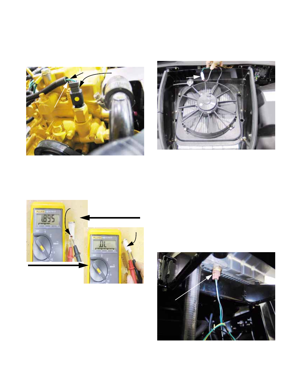
The black wire with white trace leads to the over-
temp sensor on the engine water pump. When
the coolant temperature exceeds 230 deg.f. (110
deg.c.) the contacts within the switch close, cre-
ating a path to ground. See Figure 9.32.
22.
Glow plug and Over-temp light operation:
•
The lamp contains an LED (Light Emitting
Diode). If the wires are connected to the wrong
terminals it will not work. See Figure 9.33.
•
The flat side of the lamp housing corresponds
with the ground terminal.
•
The terminal that receives power is identified
with a small red mark.
•
Polarity can be confirmed using the
diode test
feature of a DVOM: diodes pass power in only
one direction.
Figure 9.32
Over-temp
sensor
Bk/W wire
to light
Green wire to ground
Figure 9.33
Continuity: Red “+”
probe to spade terminal
marked red
Red
mark
Flat
No continuity: Red “+”
probe to spade terminal
near flat side of housing
23.
The Cooling fan (diesel only) is mounted under
the hood, atop the radiator. It is wired to blow
cool air down through the radiator core.
See Figure 9.34.
NOTE: Blowing cool air down from the top gets
the cool air to the hottest (top) part of the radia-
tor first, once the static warm air has been blown
out. This results in the greatest difference in
temperature between the air and the radiator
surface, increasing cooling efficiency.
•
The cooling fan receives power from the com-
mon spade (#3) on the fan relay (R4) through
the brown wire when the fan relay is energized.
•
The green wire goes to ground.
24.
The Fan Switch is located on the front bottom
edge of the radiator, toward the passenger’s
side. See Figure 9.35.
Figure 9.34
Cooling
fan plug
Figure 9.35
Fan switch