Chapter 2- drive system: cvt and transfer case – Cub Cadet 4 x 4 Volunteer User Manual
Page 22
Chapter 2- Drive System: CVT and Transfer Case
18
6i. Remove the wood block tool.
See Figure 2.24.
6j. Test the operation of the drive system in a
safe area, then allow the exhaust system
to cool before final assembly.
6k. Final assembly: install the cover and plug
on the driving element and replace the
parcel bin under the passenger’s seat.
DRIVE SYSTEM ADJUSTMENTS:
TRANSFER CASE SHIFT LINKAGE
1.
Before attempting any linkage repair of adjust-
ment, confirm whether the problem at hand is in
the linkage or elsewhere in the system.
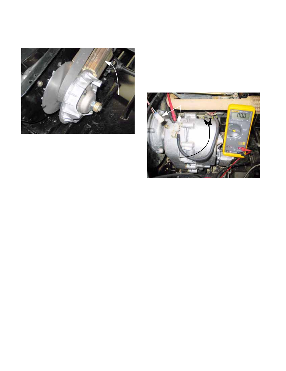
2.
A handy quick-check to confirm that the transfer
case is in neutral when the gear selector is in
neutral can be made using the two safety
switches in the starter circuit: See Figure 2.25.
2a. Locate and disconnect the harness that
leads to the neutral safety switches.
2b. Connect a DVOM or continuity light to the
pair of terminals on the disconnected har-
ness.
2c. When the transfer case is in neutral, there
should be continuity (0.0
Ω) between the
two wires in the terminal.
NOTE: There are two sets of shift forks within
the transfer case. Each shift fork has a safety
switch associated with it. When both shift forks
are in the neutral position, the contacts of both
switches will be closed. The switches are con-
nected in series, so the closure of both switches
completes the circuit.
3.
The correct operation of the switch can be con-
firmed by rotating the transfer case input shaft
and observing the reaction of the output shafts.
4.
After correct internal operation of the transfer
case is confirmed, check the linkage. Correct
any internal problems before proceeding. If the
transfer case has internal damage, no amount of
external adjustment will fix it.
Figure 2.24
Tighten bolts
and remove
block
Figure 2.25
contacts closed
in series:
Both switches
Switch harness unplugged