Cub Cadet 4 x 4 Volunteer User Manual
Page 143
Chapter 4 - Front Suspension and steering
139
11.
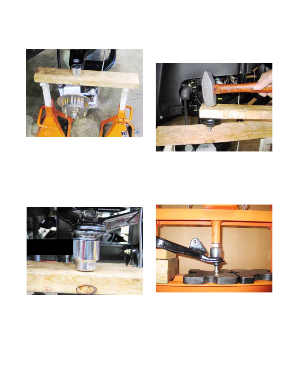
Position the new ball joint for installation:
See Figure 4.35.
11a. Position a 2x4 piece of dimensional lum-
ber between two jackstands, just beneath
the upper control arm.
11b. Insert the stud end of the new ball joint
into a 1-1/2” (38mm) socket.
11c. Position the socket and ball joint on the
board so that the socket holds the ball
joint in place for installation.
11d. Carefully drive the ball joint into the bore.
Do not damage the top lip of the bore, or
installation will be extremely difficult.
Figure 4.35
Upper control arm
supported by jack
stands, board, and
socket
Figure 4.36
Position ball joint
and socket carefully
Socket supports
ball joint by shoulder
11e. Remove the socket when it meets the bot-
tom of the upper control arm.
11f. Continue driving the ball joint until it is fully
seated. See Figure 4.37.
12.
Alternatively, if a hydraulic press is available, the
ball joint can be removed and installed on the
press. This requires upper control arm removal
and reinstallation, as described in the Upper
Control Arm section of this chapter.
See Figure 4.38.
13.
Secure the ball joint to the control arm with the
snap ring.
Figure 4.37
Drive ball joint
into upper control
arm without
damaging
either part
Figure 4.38
Use press to drive
arm over ball joint
ball joint to stick up.
leaving room for
Socket drives arm,