Chapter 9 - electrical – Cub Cadet 4 x 4 Volunteer User Manual
Page 284
Chapter 9 - Electrical
280
•
The terminals are connected to the wires identi-
fied in the above tables.
9.
Safety Switches
9a. The transmission switches are located in
a separate sub harness that consists of a
simple loop connecting the two switches
in series.
•
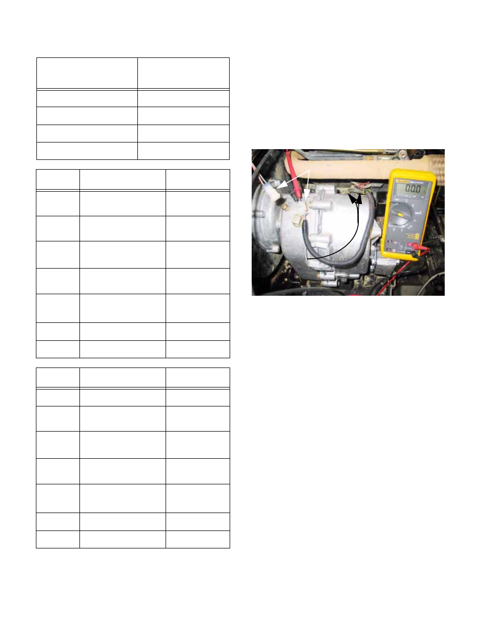
The orange and grey wires of the transmission
harness can be found just outboard of the front
edge of the transfer case. See Figure 9.9.
•
There are two sets of shift forks within the trans-
fer case. Each shift fork has a safety switch
associated with it.
When both shift forks are in the neutral position,
the contacts of both switches will be closed.
The switches are connected in series, so the clo-
sure of both switches completes the circuit.
9b. To test the transmission safety switches:
•
Confirm that the transaxle is in neutral by rotat-
ing the transfer case input shaft and observing
the reaction of the output shafts.
•
Locate and disconnect the harness that leads to
the neutral safety switches.
•
Connect a DVOM or continuity light to the pair of
terminals on the disconnected harness.
•
When the transfer case is in neutral, there
should be continuity (0.0
Ω) between the two
wires in the terminal.
•
If there is no continuity through the circuit
when the transfer case is in neutral, check the
switches individually to identify the one with con-
tacts that are open.
Key Position
Terminal
Continuity
STOP
M - G - A1
Run w/ Lights
B - A1 L - A2
Run
B - A1
Start
B - S - A1
Spade
Wire (gas)
Function
G
Green
Constant
ground
B
Red / White trace
Fused hot,
jumper to A2
A2
Red / White trace
Fused hot,
jumper to B
A1
White (2x)
Energize run
systems
S
Orange / White
trace
Initiates power
to starter circuit
M
Red / Black trace
Engine stop
L
Yellow (2X)
Headlights
Spade
Wire (diesel)
Function
G
N/A
B
Red / Black trace
Fused hot,
jumper to A2
A2
Red / Black trace
Fused hot,
jumper to B
A1
White
Energize run
systems
S
Orange / Black
trace
Initiates power
to starter circuit
M
N/A
L
Yellow (2X)
Headlights
contacts closed
in series:
Both switches
Switch (harness unplugged)
Figure 9.9