Cub Cadet 4 x 4 Volunteer User Manual
Page 111
Chapter 3 - Drive System: Drive Shafts and Differentials
107
•
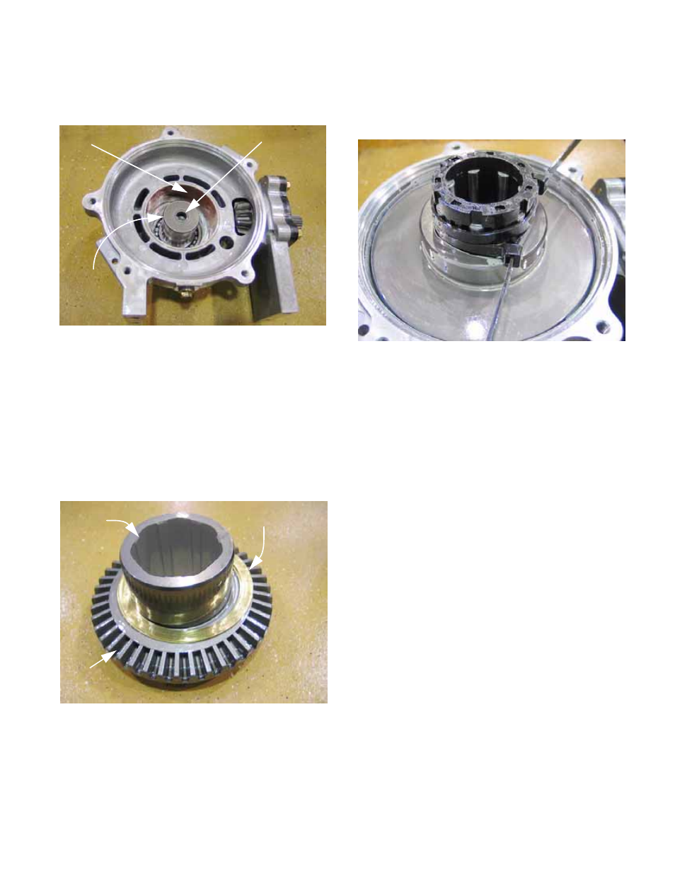
The right side drive spool is supported in a simi-
lar Timken ball bearing in the larger right-side
housing. See Figure 3.49.
•
The right side drive spool is fitted with a pilot
bearing, maintaining alignment between the two
drive spools.
•
The differential housing is lined with bearing
material. The ring gear incorporates a drum that
rides in the bearing material.
10.
The ring gear and drum contain a set of cam
grooves. The rollers ride in the grooves.
See Figure 3.50.
•
A pair of brass thrust washers help to position
the ring gear and drum.
Figure 3.49
Bearing material
sleeve
Pilot bearing
Right-side
drive spool
Figure 3.50
Cam grooves
in drum
Ring gear
Brass rings
11.
The caged rollers fit down into the drum, with the
drive spools rotating freely within the rollers, as
long as the magnet is not energized.
See Figure 3.51.
NOTE: Cable ties are used to hold the rollers in
the cage during assembly.
12.
Operation:
12a. When the magnet is energized, the cage
and rollers lag behind the rotating speed
of the ring gear because of the drag
between the toothed ring and the housing.
12b. When cage and rollers lag behind the
speed of the drum, the ramps leading into
the cam grooves drive the rollers in
against the drive spools.
12c. When the rollers are clamped between the
cam grooves and the drive spools, power
is transmitted through the drive spools.
12d. The front differential may be engaged
(energized) while the vehicle is moving,
as long as the rear wheels have not
already lost traction. If there is a great
disparity in speed between the front
wheels and the rear wheels, there is a risk
of shock failure.
Figure 3.51