Chapter 2- drive system: cvt and transfer case – Cub Cadet 4 x 4 Volunteer User Manual
Page 34
Chapter 2- Drive System: CVT and Transfer Case
30
23.
Disconnect the transfer case wiring harness
from the two neutral safety switches, and
remove it. This will prevent the harness and
switches from being damaged when the transfer
case is removed.
24.
Carefully lift the transfer case and brackets out
of the vehicle.
25.
If the transfer case is to be disassembled, it is
best to simply leave the brackets attached to the
housing, so that their position is not disturbed.
26.
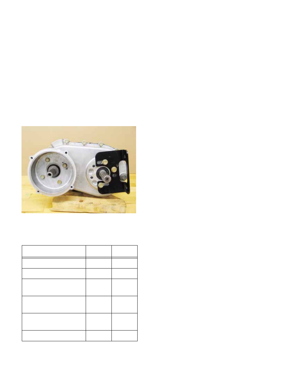
If the transfer case is to be replaced, match-
mark the position of each mounting bracket so
that it can be installed in an identical position on
the new transfer case. See Figure 2.55.
27.
Installation Notes: Transfer Case Alignment and
Positioning.
27a. Place the transfer case in the engine bay
with sufficient access to connect the
transfer case wiring harness, and install
the harness.
27b. Move the transfer case into it’s mounting
position in the drive system tray, connect-
ing the rear drive shaft to the rear output
shaft in the process.
27c. Secure the transfer case with the four sets
of 5/16” -18 nuts and bolts, but do not fully
tighten the fasteners.
27d. Connect the front drive shaft to the front
output shaft of the transfer case, and re-
attach the front differential as described in
the DRIVE SYSTEM SERVICE: DRIVE
SHAFT TO FRONT DIFFERENTIAL sec-
tion of this manual.
27e. Apply a small amount of thread locking
compound such as Loctite
R
242 (blue) to
all of the screws that hold the engine /
transmission plate to the engine and the
transfer case.
27f. Position the plate, along with the spacer
that fits between the plate and the mount-
ing boss on the engine, and secure it with
one screw to the engine and one screw to
the transfer case.
27g. Confirm that the plate is properly seated
over the mounting boss on the transfer
case, and that the screw holes are prop-
erly aligned, then install all the screws that
secure the plate and spacer. Tighten
them to the torque specified in table....
27h. Tighten all the fasteners that hold the
transfer case to the drive system cradle.
Refer to the accompanying table for
torque specifications.
28.
Installation Notes: Drive Connections
28a. Apply a sparing amount of anti-seize com-
pound to the splined joint at each end or
the rear driveshaft.
NOTE: If too much anti-seize compound is
applied to the splined connection on the back of
the transfer case, centrifugal force will sling it
onto the parking brake rotor when the vehicle is
in motion.
28b. Secure the rear driveshaft to the rear differ-
ential using a new tension pin.
Item
ft-lbs
N-m
CVT driving element
32-36
43-49
CVT driven element
70-80
95-109
Engine / transmission
plate to transmission
12
16
Engine / transmission
plate to engine
18
24
Transmission brack-
ets to engine tray
32-36
43-49
Lug nuts
65-75
88-102
Figure 2.55