Chapter 2- drive system: cvt and transfer case – Cub Cadet 4 x 4 Volunteer User Manual
Page 63
Chapter 2- Drive System: CVT and Transfer Case
59
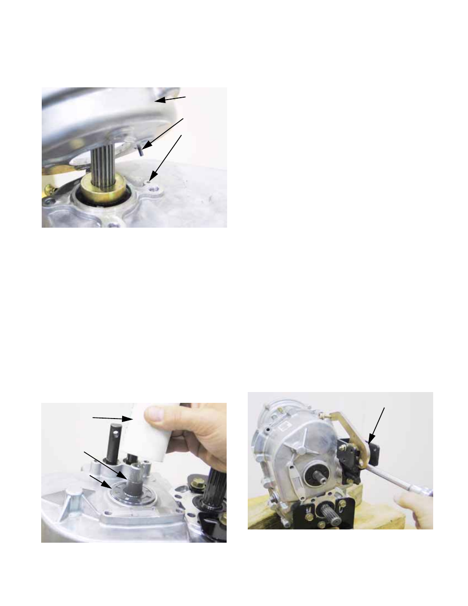
4x. Install the adaptor housing, using the ten-
sion pin to confirm proper indexing.
See Figure 2.147.
4y. Tighten the four screws that hold the adap-
tor housing to a torque of 200-260 in-lbs.
(22.6-29.4 N-m), in a “criss-cross” pattern.
NOTE: Refer to seal installation tips listed pre-
viously in this section.
4z. Install the pair of output shaft seals.
4aa. Install the pair of shift shaft seals.
4ab. Install the brake shaft seal. There is an
unusually large step in the brake shaft.
Substitute a short length of tubing for the
normal seal protector. Shipping caps from
hydraulic fittings and battery posts can be
cut to make suitable protector.
See Figure 2.148.
Figure 2.147
Adaptor
housing
Roll-pin
Roll pin bore
Figure 2.148
Seal driver
(PVC pipe)
Improvised
seal protector
Brake
shaft seal
4ac. Install the magnetic drain plug in the bot-
tom of the transfer case. Tighten the plug
to a torque of 220-280 in-lb. (25-32 N-m).
NOTE: If the sealing gasket needs replacement,
it can be ordered as part number 721-04174.
This part is not listed in the IPL.
4ad. If removed, install the vent. Tighten it 2-3
turns.
NOTE: Allow RTV sealant to cure according to
the sealant manufacturer’s instructions before
filling the case with gear lube.
4ae. Fill the case with 64 fl.oz. (1.9L) of 80W-90
Low Foam Oil (Cub Cadet P/N: 737-
04040). When full, gear lube will trickle-
out of the level plug hole.
4af. Install the level plug and tighten it to a
torque of 220-280 in-lb. (25-32 N-m).
4ag. Install the fill plug. Tighten it 2-3 turns.
NOTE: If the transfer case is to be filled after
installation, the fill plug and level plug may be
installed finger-tight. Label the transfer case
“EMPTY” in a prominent place until it is filled.
5.
Install the shift arm assembly:
5a. Apply a small amount of thread locking
compound such as Loctite
R
242 (blue) to
the screws that hold the shift arm assem-
bly to the case.
5b. Fasten the shift arm assembly to the case,
tightening the screws to a torque of 200-
260 in-lbs. (22.6-29.4 N-m).
See Figure 2.149.
Figure 2.149
Shift arm assembly