Cub Cadet 4 x 4 Volunteer User Manual
Page 106
Chapter 3 - Drive System: Drive Shafts and Differentials
102
4b. Move the hub and lower control arm out
and forward far enough to slip the end of
the axle out of the hub. See Figure 3.37.
NOTE: Use caution not to strain the brake line.
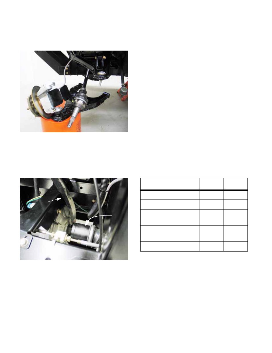
5.
The inner constant velocity joint is held into the
differential by a hog ring. Use a pry bar to pop
the joint loose from the differential.
See Figure 3.38.
CAUTION: When working on the left side of the
vehicle, be very careful not to damage the wires
that control the front differential engagement.
6.
From this point, any repairs to the drive shaft can
be made on the bench, or the shaft can be
replaced as a complete unit.
7.
Installation notes:
•
Apply anti-seize compound to the splines of the
axle before assembly.
•
Apply anti-seize compound to the bolts that hold
the lower control arm to the frame.
•
Replace any worn hardware or components
before reassembly. If the self-locking feature of
any of the nuts is degraded, replace the nuts or
apply thread locking compound such as Loctite®
242 (blue) to the threads.
•
If the locking features of nuts on the tie rod end
or ball joint stud has worn, replace the nut. Do
not use thread locking compound.
•
Assemble the front suspension by reversing the
steps of disassembly.
NOTE: Tightening the nuts and bolts that hold
the control arm to the frame locks the control
arm bushings. Lower the vehicle to the ground
so that the suspension is loaded before tighten-
ing the nuts fully. This will prevent pre-loading of
the bushings.
•
Tighten fasteners to the torques specified in the
table.
8.
Test run the vehicle in a safe area before return-
ing it to service.
Figure 3.37
Figure 3.38
Pry bar
Inner
constant
velocity
joint
Item
ft-lbs
N-m
Tie rod end
22-28
3-38
Upper ball joint
22-28
3-38
Lower control arm to
frame
32-36
43-49
Axle nut
150-
165
203-
223
Lug nuts
65-75
88-102