Chapter 8 - caterpillar engine and related systems – Cub Cadet 4 x 4 Volunteer User Manual
Page 238
Chapter 8 - Caterpillar Engine and Related Systems
234
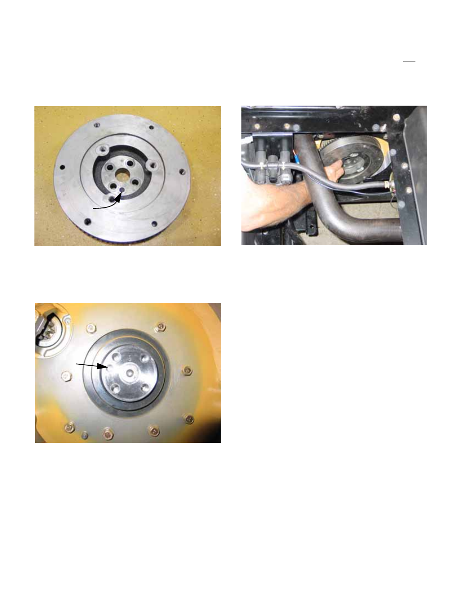
6c. Note the match-mark that indexes the fly-
wheel to the crankshaft to maintain factory
balance of the rotating assembly.
There is a cast dimple in the bolt face of
the flywheel. See Figure 8.38.
6d. The dimple corresponds to an empty
dowel bore in the crankshaft.
See Figure 8.39.
6e. Remove the flywheel bolts using a 14mm
wrench.
6f. Wiggle the flywheel or rap it with a soft
hammer to release it from the crankshaft.
See Figure 8.40.
CAUTION: Flywheel weighs 20.0 lbs. (9.1Kg.)
6g. Carefully lift or lower the flywheel out of
the vehicle. It will clear the nose of the
starter motor.
6h. Flywheel installation notes
•
The flywheel is held to the crankshaft by bolts.
Bolts work in compression. There is no dowel,
and it is better not to load bolts in shear. There
is enough friction between the drive boss on the
end of the crankshaft and the recess that it fits
into on the flywheel to transfer drive force. This
friction is maintained by the torque of the bolts.
Torque is critical. It is also critical that the
mounting surfaces be clean and free of deforma-
tions.
•
Apply a small amount of thread locking com-
pound such as Loctite® 242 (blue) to the threads
of each bolt. The thread locker acts as a lubri-
cant as the bolts are tightened.
•
Position the flywheel on the crankshaft, correctly
indexed: the dimple in the flywheel should align
with the blind dowel bore in the crankshaft.
Figure 8.38
Dimple in
casting
Figure 8.39
Dowel
bore
Figure 8.40