Chapter 2- drive system: cvt and transfer case – Cub Cadet 4 x 4 Volunteer User Manual
Page 43
Chapter 2- Drive System: CVT and Transfer Case
39
•
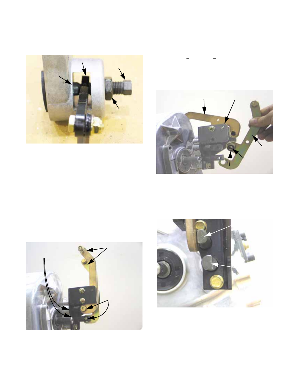
The adjustment screw acts by moving the con-
tact point that the cam arm pivots against.
See Figure 2.80.
NOTE: The brake pads are thick enough that
they will have a long service life. While service
brakes are used to stop the vehicle, parking
brakes merely hold it once it is stopped. If the
parking brakes wear prematurely, confirm that
the mechanism is not sticking in the applied
position. If it is not, operator technique (driving
with the parking brake applied) is probably the
cause.
5.
Remove the shift arm assembly:
5a. Disconnect the shift arms from the shift
shafts using a 3/16” allen wrench.
See Figure 2.81.
Figure 2.80
Adjustment
screw
Jam nut
Cam arm
“Bullet”
Figure 2.81
Shift shafts
Shift arms
Shouldered
socket-head
cap screws
5b. Loosen but do not remove the nut and bolt
that the Low-range shift arm pivots on
using a pair of 7/16” wrenches.
NOTE: Long arm = Low range
5c. Remove the nut and bolt that the Forward-
Neutral-Reverse shift arm pivots on using
a pair of 7/16” wrenches, and remove the
arm from the bracket. See Figure 2.82.
NOTE: The ends of both shift-shafts are D-
shaped. The flat of each D should be oriented
toward the arm that actuates the shaft.
See Figure 2.83.
Figure 2.82
Low gear shift arm Bracket
F-N-R
shift arm
Tube
Plastic bushings
Figure 2.83
Low range
shift shaft
F-N-R shift shaft