Chapter 8 - caterpillar engine and related systems – Cub Cadet 4 x 4 Volunteer User Manual
Page 266
Chapter 8 - Caterpillar Engine and Related Systems
262
8.
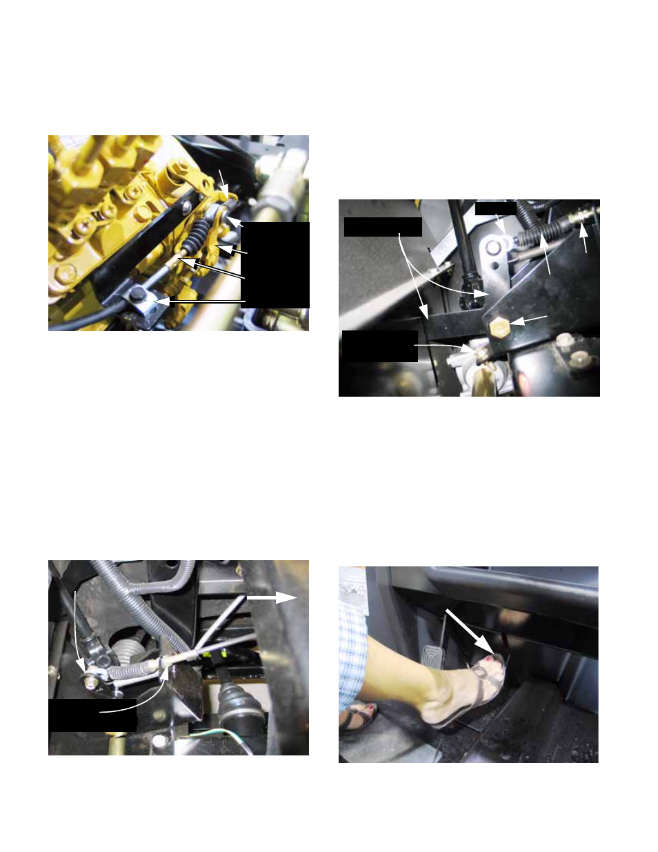
Confirm that the cable is securely clamped in
place at the engine end. The return spring
should not bind or be pulled off-center.
See Figure 8.115.
•
If the cable is to be replaced, match-mark the
location of the clamp using a paint marker. Mark
the new cable in the same location, and use that
mark to position the new cable.
•
Confirm that the cable, as mounted, has suffi-
cient travel to achieve the full range of engine
speeds from idle to top no-load RPM.
NOTE: The adjustment points for the pedal end
of the throttle cable can be reached by opening
and removing the hood.
9.
At the pedal end, the cable may be adjusted in
its bracket using a pair of 1/2” wrenches to set
proper travel. See Figure 8.116.
Final Throttle Cable Adjustment:
10.
To get full travel, adjust the pedal end of the
cable so that the eyelet on the cable core just
rests against the socket head cap screw that
passes through it. There should be 1/8” to 1/4”
travel before tension is felt on the cable.
11.
After the cable is adjusted, check the travel-stop
bolt under the pedal. See Figure 8.117.
•
The travel stop should be set to allow full-speed
operation without over-travel: the pedal stop
should limit the travel.
12.
Loosen the throttle cable clamp screw on the
bracket in front of the fuel injector pump.
13.
Have an assistant hold the throttle pedal all the
way down or block the pedal down with a weight.
The throttle pedal arm should be against the
head of the travel-stop bolt. See Figure 8.118.
Figure 8.115
Return
spring
Clevis pin
Throttle arm
Throttle cable
Cable clamp
Figure 8.116
Pedal-end
cable adjustment
Front of
vehicle
Throttle
pedal arm
Figure 8.117
Throttle pedal
travel-stop bolt
Throttle pedal
Jam nut
Throttle cable
Pivot point
eyelet
Figure 8.118
Depress gas pedal