Drive system description – Cub Cadet 4 x 4 Volunteer User Manual
Page 93
Chapter 3 - Drive System: Drive Shafts and Differentials
89
DRIVE SYSTEM DESCRIPTION
1.
Chapter 2 of this manual covers the drive sys-
tem from the engine crankshaft to the output
shafts of the transfer case. Chapter 3 covers the
drive system down-stream of the transfer case.
This includes:
•
The drive shafts from the transfer case to the dif-
ferentials
•
The front differential
•
The rear differential
•
The drive axles (half-shafts) that connect the dif-
ferentials to the wheel hubs.
2.
Drive shafts with Hooke-Spicer type universal
joints extend fore and aft from the output shafts
of the transfer case to drive the front and rear
differentials. See Figure 3.1.
3.
Both drive shafts (front and rear) are driven
whenever the transfer case is in gear, whether or
not four-wheel drive is engaged.
Figure 3.1
Spicer-hooke type U-joint
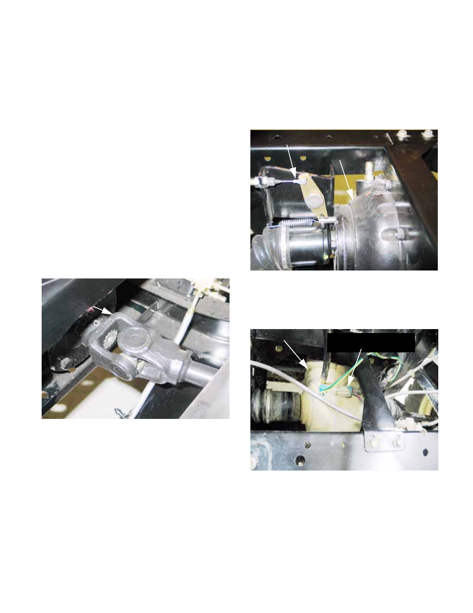
4.
The rear differential has a cast iron housing
and a cable-actuated locking feature.
See Figure 3.2.
5.
The front differential has an aluminum hous-
ing, and an electrically controlled, slip sensing
Auto-Lok® feature. See Figure 3.3.
5a. The front differential is engaged or disen-
gaged using a rocker switch on the dash-
board. An electric clutch connects the
front differential pinion to the input shaft
when energized. When de-energized, the
input shaft is still driven by the drive shaft,
but the differential free-wheels.
Figure 3.2
Differential lock
actuator
Rear differential
Figure 3.3
Front differential
Electrical connection for
Auto-Lok® feature
CHAPTER 3 - DRIVE SYSTEM: DRIVE SHAFTS AND DIFFERENTIALS