Cub Cadet 4 x 4 Volunteer User Manual
Page 129
Chapter 4 - Front Suspension and steering
125
Steering gear: See Figure 4.3.
•
The Cub Cadet Utility Vehicle has automotive
style rack and pinion steering.
•
Total travel is 3 turns from lock-to-lock.
Steering gear inspection:
1.
The steering wheel should be visually centered
in its travel, when the front wheels are facing
straight ahead.
1a. If the rack is centered in its travel but the
steering wheel is not visually centered, re-
index the wheel on the steering shaft.
1b. If the rack is not centered, make the nec-
essary adjustments at the tie-rod ends.
2.
The steering wheel should move smoothly
through the full range of travel with reasonable
effort See Figure 4.4.
Figure 4.3
steering shaft
Steering gear (rack)
Figure 4.4
Tension gauge
2a. If the steering requires more than 20 lbs.
(9.1 kg.) of force applied where the steer-
ing wheel spokes meet the rim, isolate the
steering gear from the rest of the system.
Make this test with the vehicle empty. The
front wheels should be on a smooth, dry
concrete surface.
2b. To isolate the steering gear, disconnect the
tie rod ends one at a time. Check the
effort level required to turn the steering
wheel with each tie rod separated from
the steering arm. If the steering is dispro-
portionaly easy with one tie rod discon-
nected, check the hub to see if it rotates
freely on its ball joints.
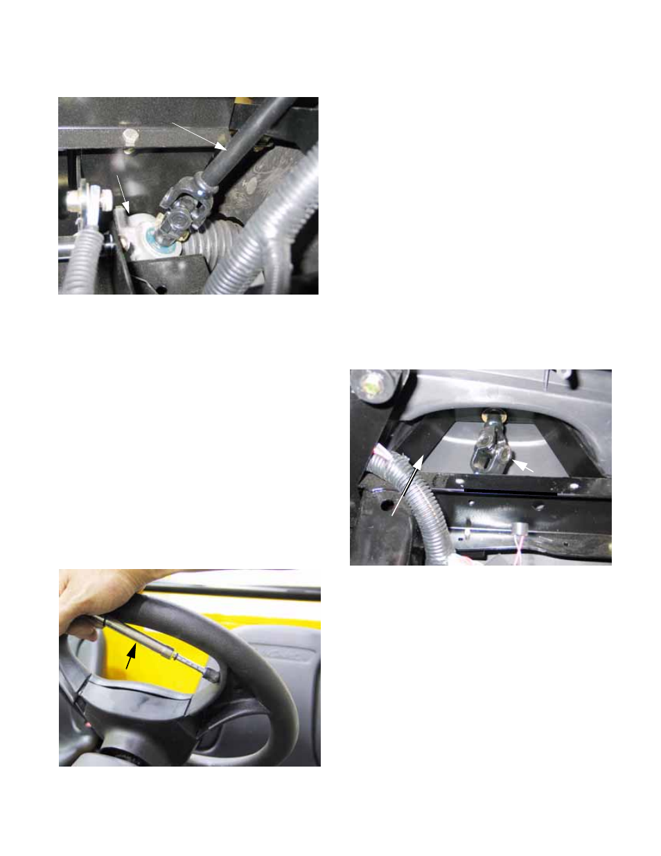
2c. If the steering wheel offers resistance at 90
degree intervals, check the two universal
joints in the steering shaft. The upper
joint operates at a much more severe
angle, and is more likely to create this
kind of symptom. See Figure 4.5.
2d. If the steering wheel motion is notchy or
stiff, the steering shaft universal joints are
not stiff, and the hubs move properly, the
problem is within the steering gear.
3.
There should be little or no play in the steering.
If play is present, work the steering wheel
against resistance at the wheels while watching
each joint in the system, including:
_Steering shaft and u-joint
_Steering rack mounts
_Wear in the steering rack itself
_Worn tie-rod ends
_Worn ball joints or control arm bushings
Figure 4.5
Steering
wheel
bracket
Upper universal joint
in steering shaft