Chapter 2- drive system: cvt and transfer case – Cub Cadet 4 x 4 Volunteer User Manual
Page 21
Chapter 2- Drive System: CVT and Transfer Case
17
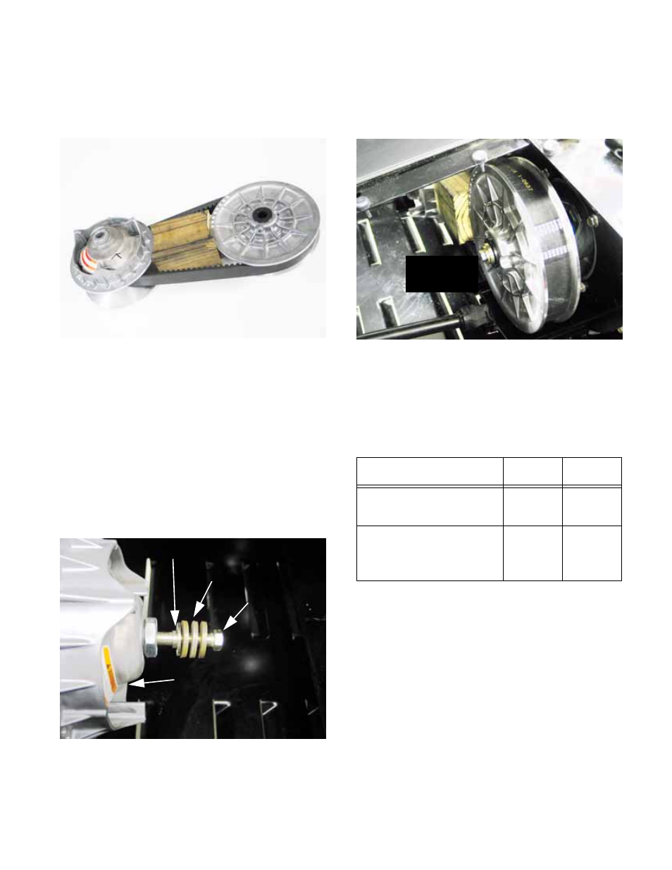
6b. Install the belt around the pulleys and insert
the wood block tool between the pulleys
to establish correct spacing.
See Figure 2.21.
6c. Install the belt and pulleys, with the wood
block between them, onto the crankshaft
of the engine and the input shaft of the
transfer case.
6d. Apply a small amount of thread locking
compound such as Loctite® 262 (red) to
the bolts that secure each pulley.
6e. Secure the driving element to the crank-
shaft using the bolt, washers, and shoul-
der spacer previously removed. Do not
tighten fully at this time. See Figure 2.22.
Figure 2.21
Wooden tool sets
spacing and holds
assembly together
for installation
Figure 2.22
Shoulder spacer
Washers
Bolt
Driving element
6f. Secure the driven element to the input shaft
using the bolt, washer, and shoulder
spacer previously removed. Do not
tighten fully at this time. See Figure 2.23.
6g. Tighten the bolts securing the pulleys to
their respective shafts in even steps,
drawing the pulleys into place.
6h. Once seated, tighten the bolts to the spec-
ified torque:
** Install with permanent thread locking compound
such as Loctite®
262 (red).
Item
ft-lbs
N-m
Driving element to
engine crankshaft
32-36**
43-49**
Driven element to
transfer case input
shaft
70-80**
95-
109**
Figure 2.23
all at once
CVT installed