Cub Cadet 4 x 4 Volunteer User Manual
Page 73
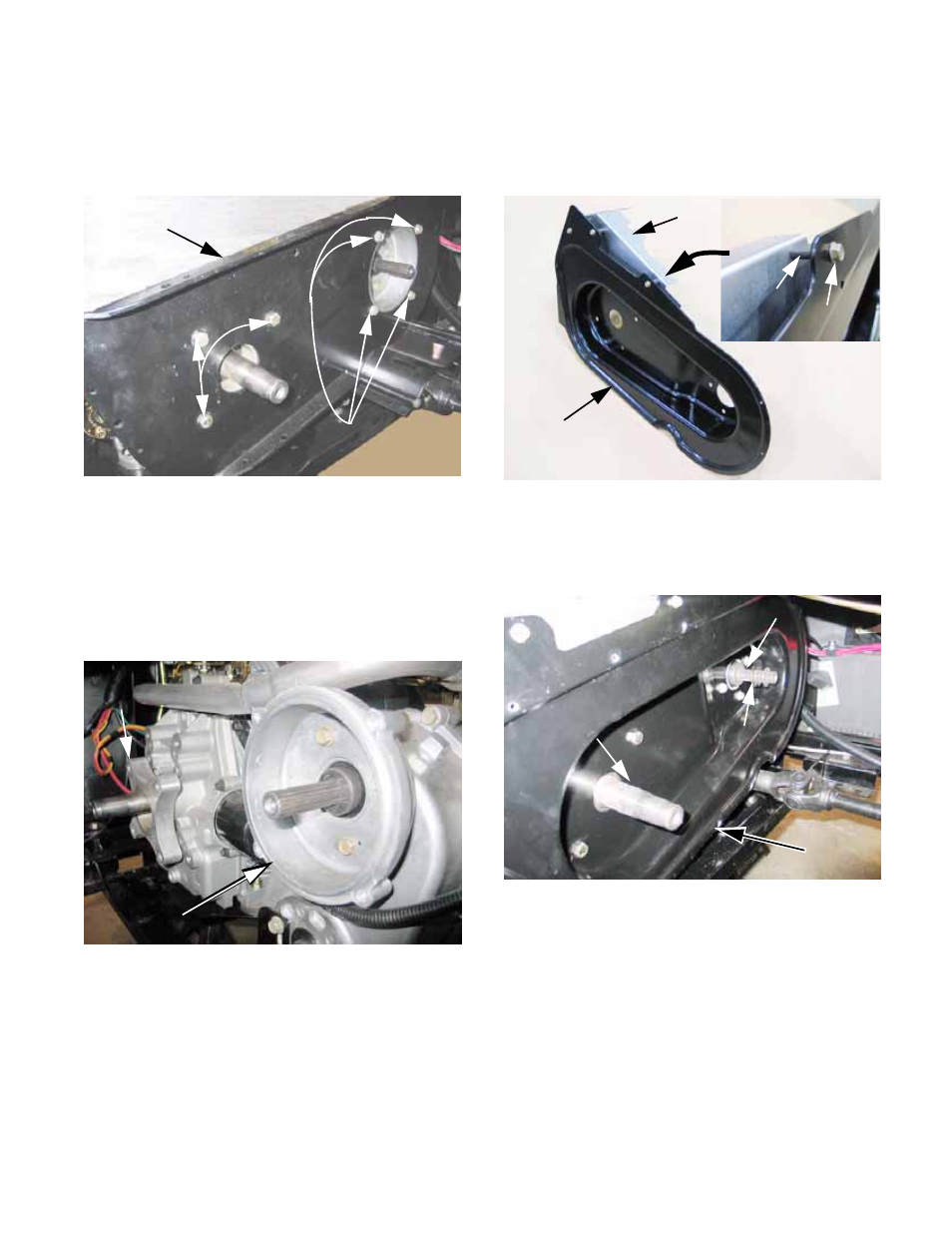
Kohler Enclosed CVT Addendum
69
5c. Loosen all the screws that hold the back
plate to the transfer case using a 1/2”
wrench. Remove all but one.
See Figure 2a.18.
5d. Remove the final two screws and carefully
lift the back plate and heat shield out of
the vehicle.
5e. Remove the adaptor from the transfer
case using a 1/2” wrench.
See Figure 2a.19.
5f. Remove the spacer from the engine. It
was held to the engine by the same
screws that held the back plate.
5g. Rivet the two parts of the heat shield
together.
Figure 2a.18
Original back plate
Screws
mounting
back plate to
engine
Screws mounting
back plate to
transfer case
Figure 2a.19
Engine
spacer
adaptor
Transfer case
5h. Attach the heat shield to the new back
plate using the 1/4-20 screws and spac-
ers. Tighten them using a 5/16” wrench.
See Figure 2a.20.
5i. Position the new back plate, connecting
the engine to the transfer case.
See Figure 2a.21.
NOTE: If the new back plate does not align prop-
erly with the mounting holes, loosen the transfer
case mounting brackets from the engine-transfer
case tray, and adjust the position of the transfer
case. DO NOT loosen the screws that hold the
brackets to the transfer case.
5j. Apply releasable thread-locking compound
such as Loctite 242® (blue) to the (4) 5/
16-18 screws and the (4) 3/8-16 screws
contained in the kit. Install the screws and
gradually tighten all of them.
Figure 2a.20
New back plate
Inset: mounting
detail
Heat
shield
Spacer
Screw
Figure 2a.21
New back plate
in position
Engine
crankshaft
Spacer washers
Transfer case
input shaft