Cub Cadet 4 x 4 Volunteer User Manual
Page 157
Chapter 4 - Front Suspension and steering
153
11.
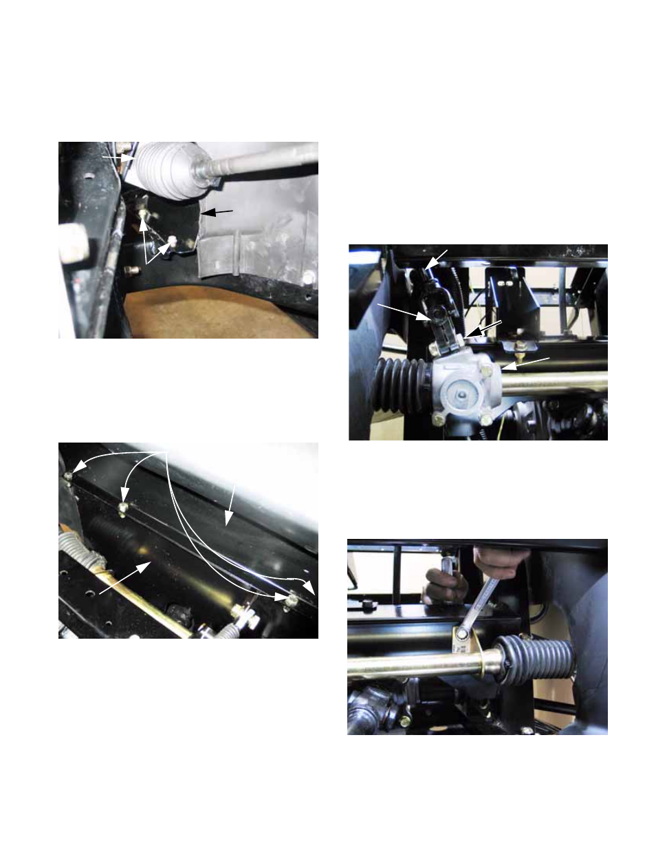
Remove the kick panel:
11a. Remove the 4 screws that hold the kick
panel to the floor using a 3/8” wrench.
See Figure 4.73.
11b. Remove the four sets of nuts and bolts
that connect the top edge of the kick
panel to the dash support panel using a
pair of 1/2” wrenches.
See Figure 4.74.
NOTE: One or both inner fenders may be
removed to improve access, at the technician’s
discretion.
Figure 4.73
Steering
gear box
Kick panel
Screws holding
left side of kick
panel to floor
Right side similar
Figure 4.74
fasteners
Kick panel
Dash support
panel
NOTE: The far left bolt can be most easily loos-
ened from below the vehicle. A socket and a
long extension can be inserted behind the left
side steering rack gaiter, just inboard of the inner
fender, to reach the nut.
11c. Lift the kick panel out of the vehicle.
12.
Remove the clamp bolt that holds the bottom
universal joint on the steering shaft to the input
shaft of the steering gear. Use a pair of 1/2”
wrenches. See Figure 4.75.
13.
Remove the bolts that hold the steering gear to
the frame using a pair of 1/2” wrenches:
13a. Two bolts hold the right side bracket.
Figure 4.75
Universal
joint
Clamp
bolt
Steering shaft
Steering gear
Figure 4.76