Chapter 9 - electrical – Cub Cadet 4 x 4 Volunteer User Manual
Page 302
Chapter 9 - Electrical
298
Digital Volt Ohm Meter
•
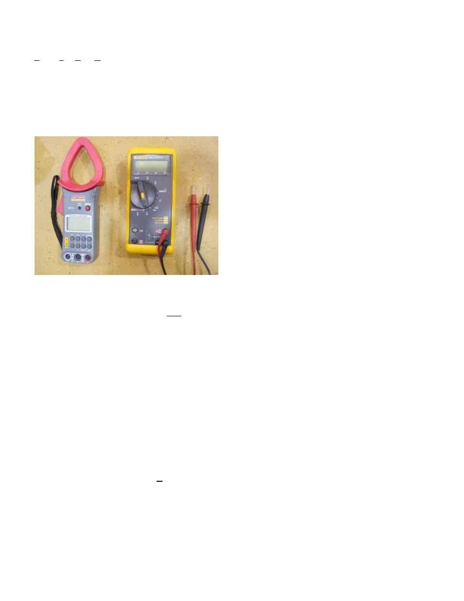
A DVOM is the most useful tool to trouble-shoot
any electrical system. There is an amazing vari-
ety of DVOMs on the market. Some are very
basic, others are tailored to specific industries,
and some high-end graphing meters function
like oscilloscopes. Even the most basic ones
are quite versatile. See Figure 9.50.
Uses:
Voltage: Set meter to read “Volts DC ( _ _ _ )” if using
an auto-ranging meter or to an appropriate scale (typi-
cally 20 Volts DC) if using a more basic model.
•
Connect the meter in parallel to the circuit
being measured, between the test point and a
known-good ground. Turn-on the circuit to be
tested, and read the meter. For most tests the
engine need not be running, but the key will be
turned-on.
•
If there is question about which end of the circuit
the electricity is coming from, the circuit may be
disconnected near the test point.
•
If the meter is connected with the polarity
reversed, a “-” will appear in front of the voltage
reading. It has no ill effects on the meter nor on
accuracy.
•
If the meter is set to Volts AC (~) it will not regis-
ter any DC voltage, but no physical harm will be
done to the meter nor the equipment being diag-
nosed. It may waste some time though.
Amperage: Most DVOMs have a very limited capac-
ity to test amperage (2-3 Amperes). When measuring
current flow, the meter must be connected in series
with the component to be measured. That means
opening the circuit and having the circuit go through
the meter.
•
Some meters have an inductive “Amp clamp”
accessory that can be used without breaking the
circuit.
•
Testing amperage beyond the capacity of the
meter can burn-out an internal fuse in some
meters. The fuses can be expensive.
Resistance: Set the meter for the “
Ω” scale.
•
Isolate the part of the circuit to be tested (discon-
nect it from the source of power).
•
Ohms are read on a scale of 0 to 1, with “0”
indicating no resistance and “1” indicating infinite
resistance.
•
Most auto-ranging meters will provide readings
on several scales. For outdoor power equip-
ment, the straight Ohm scale is most appropri-
ate. If a letter appears next to the
Ω on the
screen of the DVOM, it indicates different scales
of sensitivity.
“m” is micro-Ohms, a less sensitive scale that
effectively moves the decimal point three places
to the left of its location for plain
Ω
“M” is Meg-Ohms, a more sensitive scale that
effectively moves the decimal point three places
to the right of its location for plain
Ω
“K” is Kilo-Ohms, a more sensitive scale that
effectively moves the decimal point six places to
the right of its location for plain
Ω
•
A reading of “0” may be called “Continuity”.
A reading of “1” may be referred to as “No Con-
tinuity”.
•
Mistaken Ohm readings most frequently come
from bad technique. Poor connections between
the probes and the point to be read can throw-off
readings. False readings can be generated if
the technician touches both probes with their fin-
gers while taking the reading.
•
Diodes are effectively a one-way valve for elec-
tricity. A good diode will have continuity through
it in one direction, but not the other. Otherwise,
polarity is of no importance.
CAUTION: The meter has it’s own power source
to measure resistance. connecting the meter to
a component that has current going through it
will damage the meter (usually beyond repair).
Figure 9.50