Cub Cadet 4 x 4 Volunteer User Manual
Page 287
Chapter 9 - Electrical
283
•
The connector is most easily reached by remov-
ing the right rear wheel and the splash shield
behind the right rear wheel.
•
The wires are as described in the following table:
NOTE: The red wires from the starter solenoid
and regulator/rectifier out-put both contain
diodes. Continuity can be tested in one direction
(to the fuel solenoid), but not the other.
14.
The Starter motor on the Caterpillar engine is
located on the outboard side of the engine block,
near the front of the engine. The starter solenoid
is part of the starter. See Figure 9.14.
•
Refer to the Caterpillar Engine and Related sys-
tems Chapter of this manual for specific removal
instructions.
Wire in
main
harness
Wire in
engine
harness
Function
Red
Blue wire
and red
wire
Starter solenoid trigger
wire
Yellow
Green
Oil pressure sender
Red with
black
trace
White
Magneto ground
Orange
Red wire
and pur-
ple wire
Current to charge bat-
tery and power acces-
sories
Figure 9.16
15.
The Alternator / Regulator / Rectifier of the
Caterpillar engine is mounted at the rear of the
outboard side of the engine. See Figure 9.17.
•
Refer to the Caterpillar Engine and Related sys-
tems Chapter of this manual for specific removal
instructions.
•
Refer to the Testing the Charging System sec-
tion of this chapter for methods of testing the
charging system.
•
The alternator used in this application is Cater-
pillar-specific. It is similar to Cub Part number
BS-825084. Substituting this 40 amp alternator
for the Caterpillar 45 amp alternator will result in
a reduction in charging system capacity.
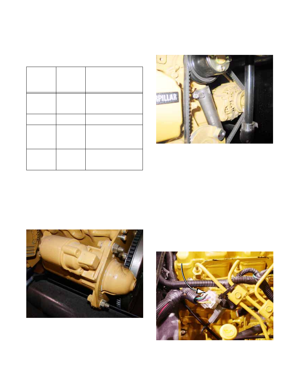
16.
Engine harness connector for the Caterpillar
engine is secured to the fuel rail on the top of the
engine. See Figure 9.18.
Figure 9.17
Figure 9.18
Caterpillar engine
harness connector