Chapter 2- drive system: cvt and transfer case – Cub Cadet 4 x 4 Volunteer User Manual
Page 47
Chapter 2- Drive System: CVT and Transfer Case
43
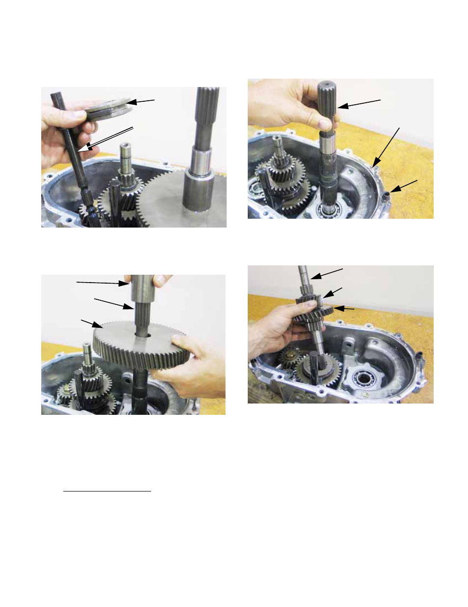
9c. Lift the low gear shift shaft assembly (shift
shaft and fork) out of the right side hous-
ing. See Figure 2.96.
9d. Lift the spacer and 69-tooth bull gear off of
the output shaft. See Figure 2.97.
NOTE: If new middle shaft gears that mate with
the bull gear or reverse idler are installed in the
transfer case, orientation of the gears on the
shaft is unimportant. Once a wear pattern is
established on the gear teeth, orient the gears to
maintain that wear pattern. It may be necessary
to mark the gear to identify its original orienta-
tion.
Figure 2.96
Low gear
shift collar
Low gear
shift shaft
Figure 2.97
Spacer
Output shaft
Bull gear
(final gear)
9e. Lift the output shaft out of the housing.
9f. Lift the middle shaft assembly out of the
housing. See Figure 2.99.
9g. The middle shaft assembly consists of:
•
The middle shaft.
•
The 26-tooth final pinion. The final pinion is held
onto a splined section of the middle shaft by a
snap ring. The flat side of the pinion faces the
ring, while the shouldered side of the pinion
abuts the high gear.
•
The 33-tooth high gear spins freely on the mid-
dle shaft, held in-place by the final pinion. The
teeth that engage the shift dog face the teeth on
the middle shaft that drive the shift dog.
•
The snap ring.
Figure 2.98
Output shaft
Right side case half
Alignment
dowel
Figure 2.99
Middle shaft
Final pinion
33-tooth forward
(High) gear