Chapter 6 - hydraulic brakes – Cub Cadet 4 x 4 Volunteer User Manual
Page 189
Chapter 6 - Hydraulic Brakes
185
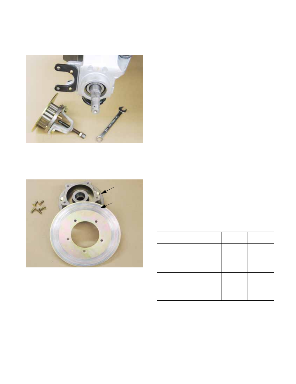
5.
Use the puller to draw the hub and rotor assem-
bly off of the axle and hub carrier (upright)
assembly. See Figure 6.31.
6.
Once removed from the vehicle, the rotor can be
separated from the hub using a 7/16” wrench.
See Figure 6.32.
Figure 6.31
Figure 6.32
Wheel hub
Brake rotor
7.
Installation notes: brake rotor
7a. Inspect the axle splines, hub splines,
wheel studs, and axle threads before
assembly. Replace any suspect compo-
nents.
7b. Apply a small amount of thread locking
compound such as Loctite® 262 (red) to
the bolts that hold the brake rotor to the
hub, prior to assembly. Tighten the bolts
to a torque of 10 ft-lbs (14 N-m).
7c. Apply a small amount of anti-seize com-
pound to the hub splines before installa-
tion.
7d. Install the brake rotor hub, washer, and
axle nut
7e. Tighten the axle nut to a torque of 150-165
ft-lbs. (203-224 N-m) and secure with new
5/32” x 1.25” (4mm x 32mm) cotter pin.
7f. Install the brake caliper as described in the
Brake Pads section of this manual.
NOTE: The axle nut torque sets the pre-load on
the wheel bearings. Improper tightening of the
axle nut will decrease wheel bearing life.
8.
Bleed the hydraulic system if necessary.
9.
Install the wheels, and lower the vehicle to the
ground.
10.
Test-drive the vehicle in a safe area before
returning it to service.
* Apply anti-seize compound
*** Apply permanent thread-locking compound
Item
ft-lbs
N-m
Caliper slide pins*
22-26
30-35
Brake rotor to wheel
hub bolts***
10
14
Axle nut
150-
165
203-
223
Lug nuts
65-75
88-102