Rear half shaft removal – Cub Cadet 4 x 4 Volunteer User Manual
Page 114
Chapter 3 - Drive System: Drive Shafts and Differentials
110
6.1.
Test-run the vehicle in a safe area before return-
ing it to service.
** Install with permanent thread locking compound
such as Loctite®
262 (red).
* Install with releasable thread locking compound
such as Loctite®
242 (blue).
REAR HALF SHAFT REMOVAL
1.
Failure mode, cause, and remedy:
•
The Rzeppa type constant velocity joints at each
end of the front half shafts are protected by rub-
ber boots. If a boot gets torn, the joint will be
damaged quite rapidly by any foreign material
that gets into the joint. Replace the joint if a boot
is compromised for any significant length of time.
•
Heat is the enemy of rotating joints. These joints
should be kept clean to dissipate heat. Avoid
pressure washing. Wipe the joints clean when
they become dirty.
•
If a joint begins to click, that is a sign that the
internal races have troughs worn into them. The
clicking is the sound of the balls that transmit
force between the inner and outer races passing
over the trough. A Rzeppa joint that clicks as
the steering or suspension travel through their
range of motion has worn, and should be
replaced.
•
At the time of printing, it is uncertain if replace-
ment axle components will be available:
- Replacement boots may be available for instal-
lation on the constant velocity joints
- Replacement joints may be available for instal-
lation on the axles.
- If replacement of a constant velocity joint
becomes necessary, the complete axle (half
shaft) may be the only service option.
2.
Preparation for removal of a rear axle:
2a. If an impact wrench is unavailable:
•
Engage the differential lock and apply the park-
ing brake.
•
Loosen the lug nuts on the wheel driven by the
axle that is to be replaced using a 3/4” wrench.
2b. Lift and safely support the rear of the vehi-
cle.
2c. Tilt the cargo box up.
2d. Remove the rear wheel. See Figure 3.56.
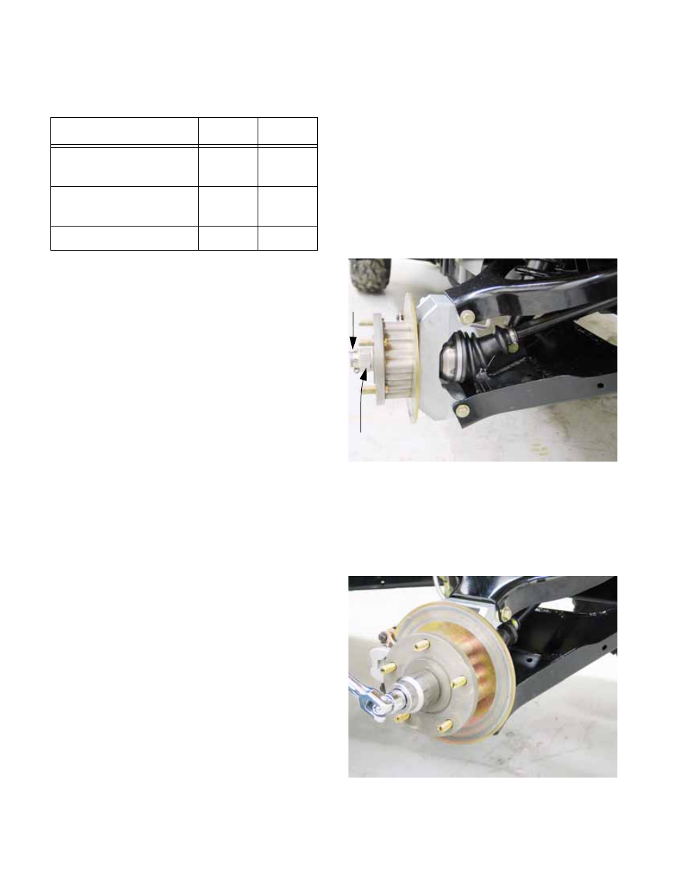
3.
Remove and discard the cotter pin that locks the
axle nut.
4.
Remove the axle nut and flat washer using a 1-
5/16” wrench. Reinstall the nut finger-tight to
protect the threads. See Figure 3.57.
Item
ft-lbs
N-m
Torque bracket to
frame
16-20
22-27
Torque bracket to dif-
ferential
20-22**
27-30**
Differential to frame
32-36** 43-49**
Figure 3.56
Axle nut
Cotter pin
Figure 3.57