Chapter 2- drive system: cvt and transfer case – Cub Cadet 4 x 4 Volunteer User Manual
Page 59
Chapter 2- Drive System: CVT and Transfer Case
55
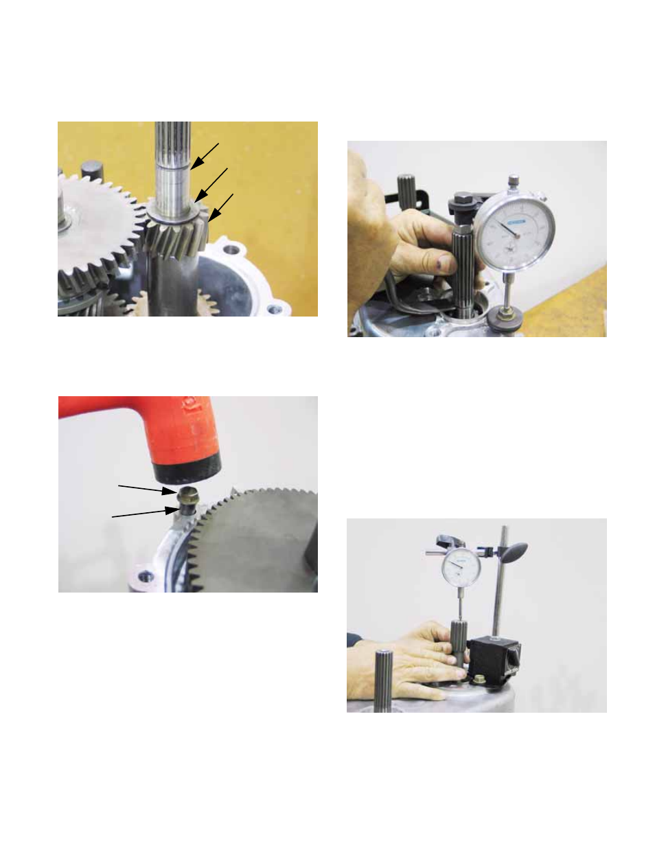
3y. Install the low pinion on the input shaft, fol-
lowed by the .060” (1.52mm) flat washer.
See Figure 2.134.
3z. Install the alignment dowels in the
untapped holes of the mating surface of
the right side case half. See Figure 2.135.
3aa. Lower the left side case half over the gear
set, so the sealing surfaces of the two
case halves meet.
3ab. Fasten the two case halves together using
four of the 5/16”-18 screws previously
removed. Tighten the screws “snug” but
they need not be torqued.
Figure 2.134
Input shaft
Flat washer
Low pinion
Figure 2.135
Bolt used
as a driver
Alignment
dowel
4.
Checking and final assembly:
4a. Affix a dial indicator to the input shaft, so
that it reads against the case.
See Figure 2.136.
4b. Work the input shaft up and down to get
and end-play measurement on the dial
indicator. End play should be less than
.009” (.23mm) without pre-loading the
input shaft bearing.
•
If end play is greater than .009” add .010”
(.254mm) shim P/N: 736-0563 to correct.
4c. Affix the dial indicator to read the end-play
of the axle shaft. A mag-base is suitable.
See Figure 2.137.
Figure 2.136
Checking input shaft end-play
Figure 2.137
Checking axle
shaft end-play