Chapter 9 - electrical – Cub Cadet 4 x 4 Volunteer User Manual
Page 306
Chapter 9 - Electrical
302
2e. Interpretation:
If the ohm meter indicates no continuity
between the two the purple stator leads,
there is a fault in the stator windings.
If the ohm meter indicates continuity
between either purple stator lead and
ground, the stator windings are shorted
to ground.
NOTE: If there is an intermittent charging sys-
tem problem, perform these tests when the
engine is cold, and again when the engine is hot.
NOTE: Low voltage readings may also result
from poor test connections or low engine RPM.
3.
If the Kohler stator is good, test the amperage
out-put from the regulator / rectifier.
3a. Attach a DC shunt with DVOM or an
ammeter capable of reading up to 25
amperes of DC current. The most accu-
rate point to take a reading will be at the
battery ground cable.
3b. The Kohler 15 amp system should pro-
duce 15 amps with the engine running at
3,600 RPM.
3c. Connect a load tester between the battery
terminals.
3d. With the engine running at 3,600 RPM,
energize the load tester to draw amper-
age from the system.
3e. Read the amperage on the meter.
NOTE: Output varies with load. A fixed-load
battery tester can be used to apply enough load
to test the charging system out-put.
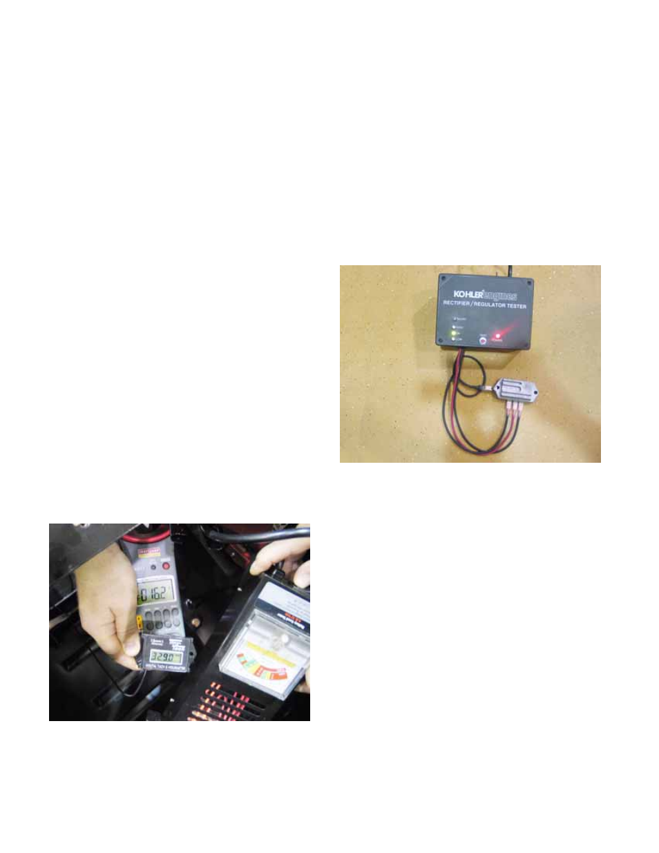
3f. With the engine off, connect Kohler tool
#25 7651-20 to the regulator/rectifier:
The two black leads go to the terminals
normally connected to purple stator
leads.
The red lead goes to the center terminal
(B+).
The ground clip goes to ground.
3g. Plug the tester into a 110V AC outlet, turn
it ON and push the test button until it
clicks. Repeat the test to confirm.
3h. Read the illuminated jewel for the verdict.
NOTE: A flashing “LOW” jewel may result from a
poor ground connection.
NOTE: If the regulator rectifier is being tested in-
situ on the engine, check the ground quality
using the voltage drop test described elsewhere
in this section.
4.
Checking the Caterpillar charging system:
4a. The Caterpillar alternator is belt driven.
Confirm that the belt is not slipping before
assessing the alternator.
4b. Attach a DC shunt with DVOM or an
ammeter capable of reading up to 25
amperes of DC current. The most accu-
rate point to take a reading will be at the
battery ground cable.
4c. Connect a load tester between the battery
terminals.
Figure 9.59
Figure 9.60