Cub Cadet 4 x 4 Volunteer User Manual
Page 149
Chapter 4 - Front Suspension and steering
145
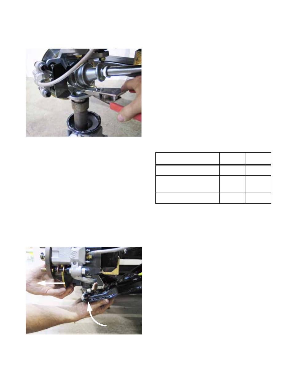
11d. Secure the new ball joint with a new retain-
ing ring. See Figure 4.51.
12.
Fasten the lower control arm to the frame of the
vehicle.
•
Both bolts enter the pivot points from the front.
•
Only the fore-most bolt has a flat washer
beneath its head.
•
If the locking feature of the nuts has worn,
replace the nuts or apply a small amount of
thread locking compound such as Loctite® 242
(blue) to the threads. Do not tighten the nuts at
this point.
13.
Pull outward on the bottom of the hub to align
the tapered stud on the ball joint with the tapered
bore that it mates with in the lower control arm.
See Figure 4.52.
Figure 4.51
Figure 4.52
Pull
Push
14.
Secure the ball joint stud to the hub assembly,
tightening the nut to a torque of 22-28 ft-lbs (30-
38 N-m). If the locking feature of the nut has
worn, replace the nut.
15.
Prop, or jack-up the front suspension to get the
upper control arm roughly horizontal, then
tighten the nuts at the lower control arm/frame
pivot point to a torque of 32-36 ft-lbs. (43-49 N-
m).
NOTE: This will lock the bushings near the static
ride height so that they are not under a constant
torsional load (pre-loaded).
16.
Install the wheel, and tighten the lug nuts to a
torque of 75 ft-lbs (102 N-m).
17.
Lower the vehicle to the ground.
18.
Check alignment, and test drive the vehicle in a
safe area before returning it to service.
Lower Control Arm (and bushings)
NOTE: Refer to the Lower Ball Joint section of
this chapter when removing and installing the
lower control arm. The lower control arm is
removed as part of this procedure.
NOTE: If lower control arm bushings are to be
replaced, refer to the part of the upper control
arm procedure that concerns bushing replace-
ment. The bushing part numbers and replace-
ment procedures are identical.
Item
ft-lbs
N-m
Ball joint stud nut
40-45
54-61
Lower control arm
mounting bolts
32-36
43-49
Lug nuts
65-75
88-102