Cub Cadet 4 x 4 Volunteer User Manual
Page 216
Chapter 7 - Kohler Engine Service Access and Fuel System
212
9.
After the idle and throttle stop are set, check and
adjust top no-load speed. See Figure 7.49.
•
Apply light force to the governor input arm bring-
ing it against the stop.
•
The engine should reach 3,850 RPM.
•
If adjustment is necessary, use a pair of 6mm
wrenches to adjust the length of the bolt that
transfers movement from the governor input arm
to the silver-colored intermediate governor arm.
10.
Eliminate any linkage bind and play before
attempting to adjust the linkage:
•
Clean, lubricate, or replace the cable if neces-
sary to achieve proper function.
•
Clean, lubricate, or repair the pedal assembly as
necessary to achieve proper function. Dry lubri-
cants such as graphite or PTFE are preferred.
11.
Confirm that the cable is securely clamped in
place at the engine end. See Figure 7.50.
•
If the cable is to be replaced, match-mark the
location of the clamp using a paint marker. Mark
the new cable in the same location, and use that
mark to position the new cable.
•
Confirm that the cable, as mounted, has suffi-
cient travel to achieve the full range of engine
speeds from idle to top no-load RPM.
NOTE: The adjustment points for the pedal end
of the throttle cable can be reached by opening
and removing the hood.
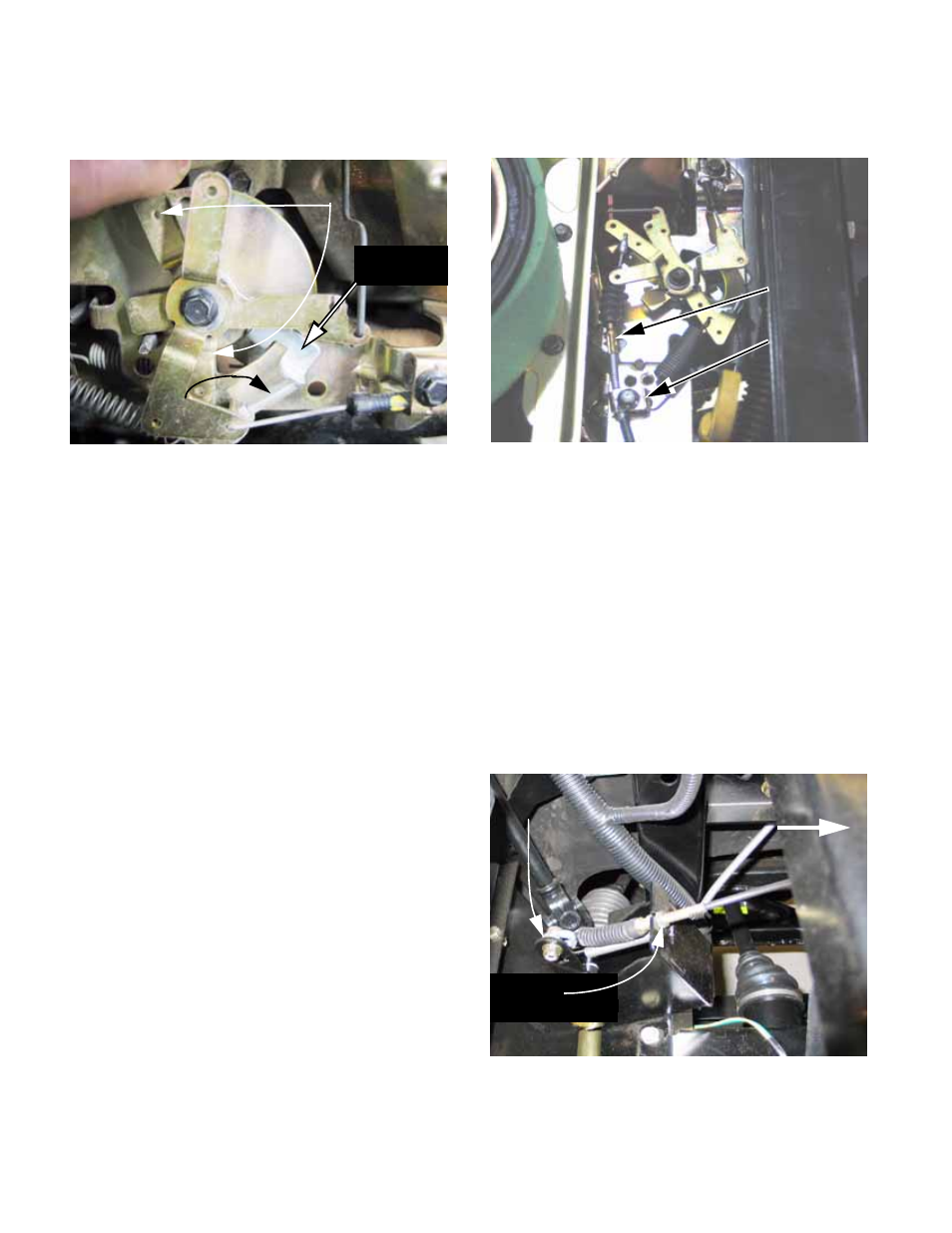
12.
At the pedal end, the cable may be adjusted in
its bracket using a pair of 1/2” wrenches to set
proper travel. See Figure 7.51.
Figure 7.49
Governor input arm
adjustment screw
Top no-load speed
governor arm
Intermediate
Figure 7.50
Throttle cable
Cable clamp
Figure 7.51
Pedal-end
cable adjustment
Front of
vehicle
Throttle
pedal arm