Chapter 2- drive system: cvt and transfer case – Cub Cadet 4 x 4 Volunteer User Manual
Page 45
Chapter 2- Drive System: CVT and Transfer Case
41
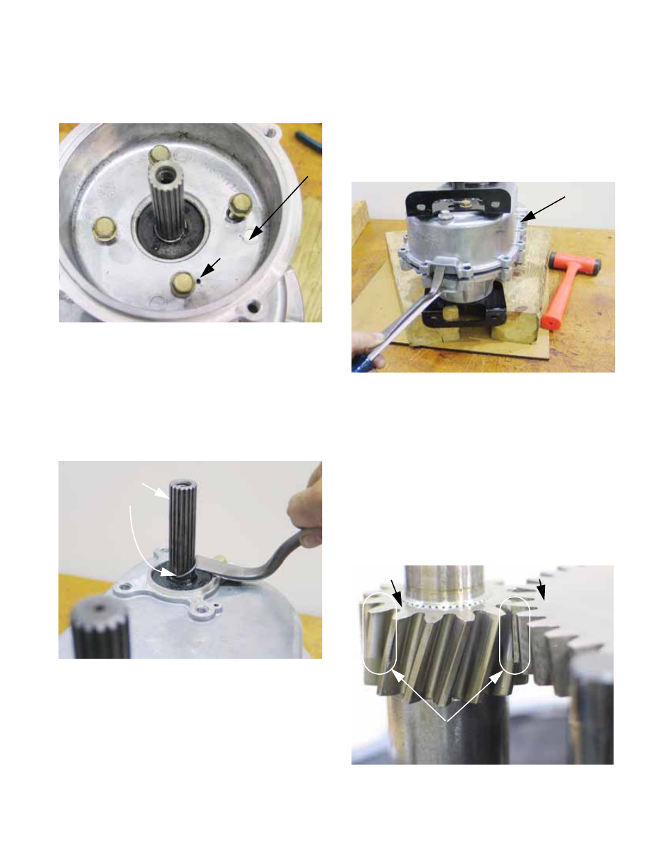
7c. Remove the four screws that hold the
adaptor housing to the transfer case using
a 1/2” wrench. See Figure 2.88.
7d. Lift the adaptor housing off of the transfer
case, noting the tension pin that indexes
the two housings to each-other.
7e. Pry or cut the hog ring off of the input
shaft. Discard the hog ring and replace it
with a new one when the transfer case is
being assembled. See Figure 2.89.
Figure 2.88
Adaptor
housing
Tension
pin
Figure 2.89
Input shaft
Hob ring
7f. Remove the screws that hold the case
halves together using a 1/2” wrench.
7g. Gently separate the case halves using the
three pry points, and a soft hammer if nec-
essary. Do not pry against the mating sur-
faces to separate the case halves.
See Figure 2.90.
NOTE: The portion of the case that was lifted-off
is identified as the “Left Case Half”. The other is
the “Right Case Half”.
8.
Input shaft:
NOTE: If new pinion gears, and the middle shaft
gears that mate with them are installed in the
transfer case, orientation of the gears on the
shaft is unimportant. Once a wear pattern is
established on the gear teeth, orient the gears to
maintain that wear pattern. See Figure 2.91.
Figure 2.90
Lift left case half
Right case
half (down)
Figure 2.91
Pinon gear Middle shaft gear
NOTE: wear pattern