Chapter 6 - hydraulic brakes – Cub Cadet 4 x 4 Volunteer User Manual
Page 191
Chapter 6 - Hydraulic Brakes
187
5.
Remove the left front fender from the vehicle:
See Figure 6.35.
6.
Remove the 3 sets of nuts and bolts attaching
the fender to the frame uprights using a pair of
7/16” wrenches.
7.
Remove the 3 self tapping screws attaching the
fender to the lower portion of the frame using a
1/2” wrench.
8.
Pull the fender out of the channels (frame
uprights) that locate it, and lift it away from the
vehicle.
9.
Loosen the jam nut using a 1/2” wrench.
10.
Remove the hairpin clip and clevis pin that con-
nect the brake yoke to the brake pedal arm.
See Figure 6.36.
10.1. Place a catch pan to collect any leaking fluid.
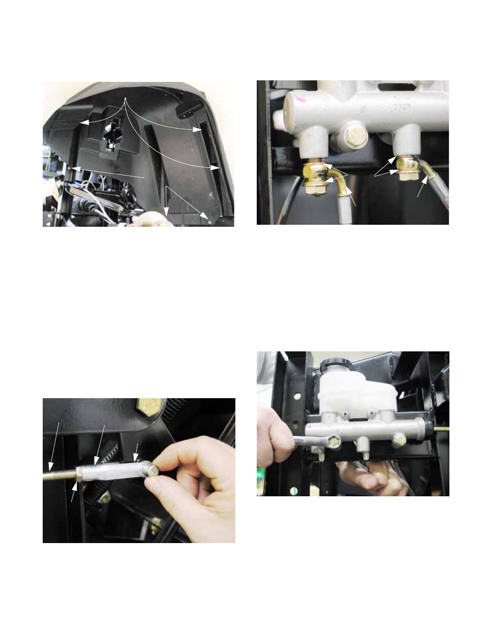
Figure 6.35
Left front
fender
Self-tapping screws
Nuts / bolts
Figure 6.36
Clevis pin
Push rod
Jam nut
Yoke
11.
Disconnect the brake lines using a 1/2” wrench.
See Figure 6.37.
NOTE: The front circuit is connected with a 90
degree elbow. The rear circuit is connected with
45 degree elbow.
NOTE: Inspect the copper washers sandwiching
the fitting on the banjo bolt. If the sealing face of
any washer is not indented, it may be reused.
It is recommended to replace the washers when-
ever the banjo fitting is disconnected.
12.
Remove the master cylinder: See Figure 6.38.
12a. First loosen, then remove the mounting
bolts using a pair of 1/2” wrenches.
12b. Pivot the master cylinder up at the front to
clear the frame, then lift it out of the vehi-
cle.
Figure 6.37
Copper
washers
front rear
90 degree 45 degree
Figure 6.38