Cub Cadet 4 x 4 Volunteer User Manual
Page 105
Chapter 3 - Drive System: Drive Shafts and Differentials
101
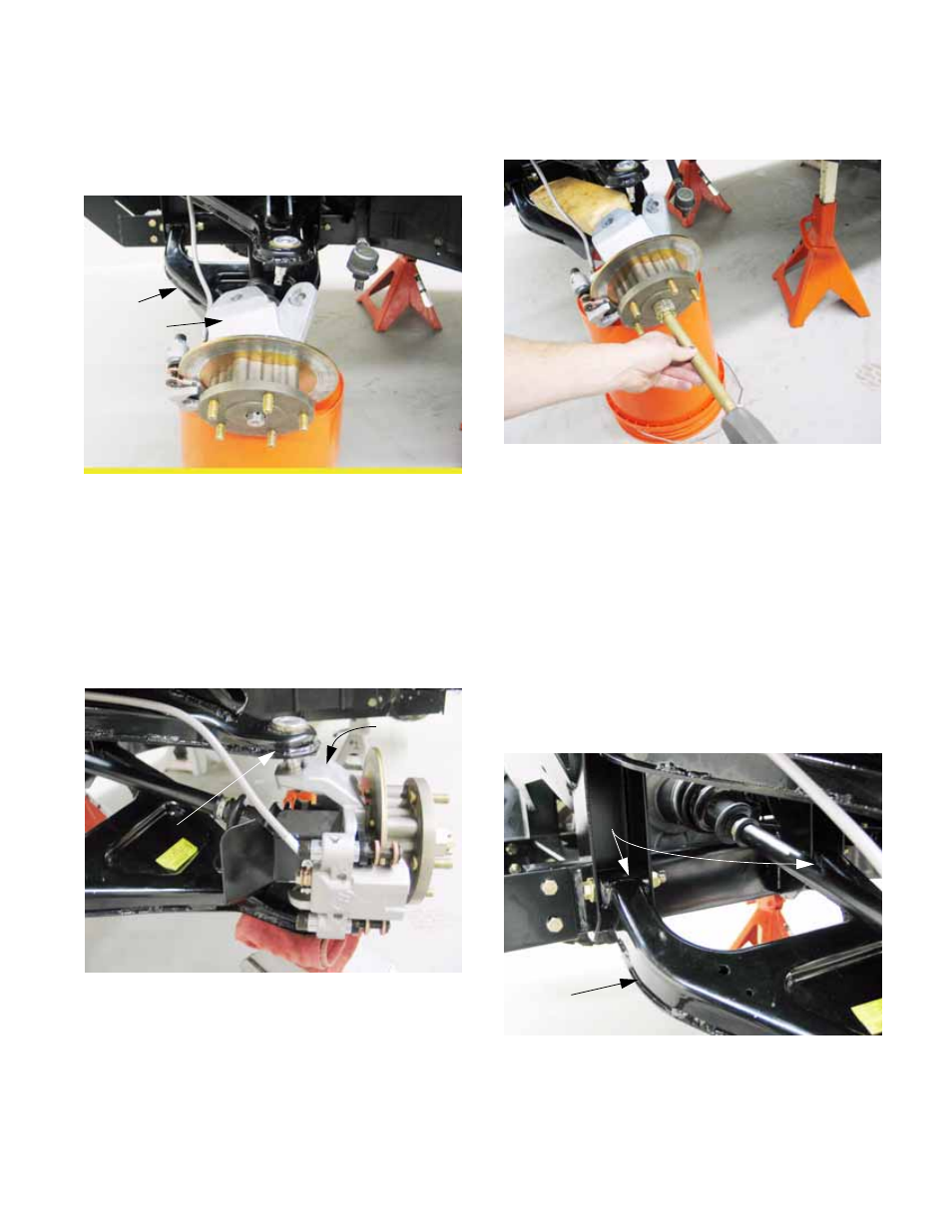
3d. Support the lower control arm and the hub
with enough stability that they will not fall,
yet allow some freedom of movement.
See Figure 3.33.
CAUTION: Do not allow the brake line to sup-
port any weight or take any pulling force.
3e. Separate the upper ball joint from the hub.
A ball joint separator of a heavy cold
chisel can be driven between the arm and
the hub to wedge the pieces apart.
See Figure 3.34.
CAUTION: Do not strike the hub casting to
release the tie rod end.
3f. Loosely thread the axle nut back onto the
end of the axle to help prevent damage to
the threads.
Figure 3.33
Lower
control
arm
Front hub
Figure 3.34
Upper ball joint
Front hub
3g. Use a soft drift to drive the axle out of the
hub. See Figure 3.35.
NOTE: Positioning a length of 2 X 4 dimensional
lumber to brace the hub will make the job easier.
NOTE: Disconnecting one ball joint does not
provide enough clearance to allow the driveshaft
to come out. At this point, the lower ball joint
may be disconnected, or the lower control arm
can be removed from the vehicle with the hub.
It is generally easier to remove the control arm.
4.
Remove the lower control arm:
4a. Remove the nuts and bolts that hold the
lower control arm to the frame using a pair
of 9/16” wrenches. See Figure 3.36.
NOTE: The bolts enter from the front, nuts to the
rear. The front bolt has a flat washer under it’s
head.
Figure 3.35
Figure 3.36
Lower
control arm
Connection
points to
frame