Chapter 2- drive system: cvt and transfer case – Cub Cadet 4 x 4 Volunteer User Manual
Page 20
Chapter 2- Drive System: CVT and Transfer Case
16
4b. Place the transfer case in H position, and
set the parking brake.
4c. Loosen the bolt that holds the driven ele-
ment to the input shaft using a 9/16”
wrench.
NOTE: Hold the driven element from rotating
using a pin spanner, if needed.
4d. Remove the bolt and washers.
4e. At this point, the driven element may be
slipped off of the transfer case input shaft.
5.
CVT Installation
NOTE: The driving element and driven element
can be installed individually, then the belt can be
rolled-on as described in the belt removal sec-
tion of this chapter.
Alternatively, both elements and the belt can be
installed all-at-once using a simple wood-block
tool. This method is described in the following
steps.
Preparation and torque specs remain the same
for both methods.
6.
Make the wood block spacer as described in the
accompanying illustration. See Figure 2.19.
6a. Prepare the CVT for installation:
•
Clean the shafts and the surrounding area
before installing the CVT.
•
Confirm the presence of the .060” (1.5mm)
spacer on the shaft between the driven element
and the transfer case housing.
•
A small amount of anti-seize compound may be
used on the splined joint between the input shaft
of the transfer case and the driven element.
•
The tapered joint between the driving element
and the crankshaft must be clean and dry.
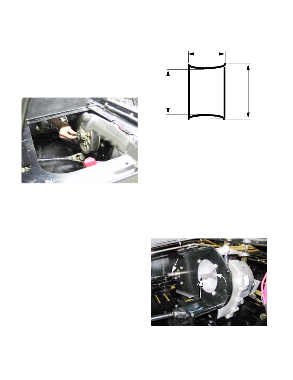
Figure 2.18
Figure 2.19
4-3/8”
NOTE: BLOCK ENDS MAY BE
V-SHAPED OR CURVED
(8.6CM)
3-1/2” (8.9CM)
(13.1CM)
5-1/8”
Figure 2.20
Tapered shaft
Splined shaft
Spacer