Installation, Electrical installation − connections – Lenze 8200 motec frequency inverter 0.25kW-7.5kW User Manual
Page 40
Installation
Electrical installation − Connections
4−15
L
EDB82MV752 EN 5.2
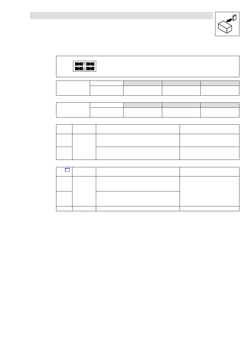
Jumper setting for outputs
10
9
8
7
2
1
4
3
j6
5
Lenze setting (see bold print in tables)
1 − 3
2 − 4
7 − 9
8 − 10
X3.1/62
Analog output, AOUT1
Possible levels
0 ... 10 V
0 ... 20 mA
4 ... 20 mA
Jumper
1 − 3
3 − 5
3 − 5
Code
C0424/1 = 0
C0424/1 = 0
C0424/1 = 1
X3.1/63
Analog output, AOUT2
Possible levels
0 ... 10 V
0 ... 20 mA
4 ... 20 mA
Jumper
2 − 4
4 − 6
4 − 6
Code
C0424/2 = 0
C0424/2 = 0
C0424/2 = 1
X3.1/
−5−
Signal type
Function
Level
(Lenze setting, in bold print)
1U/2U
Analog inputs
Actual or setpoint inputs (master voltage)
Use jumper and C0034 to change range
0 ... +5 V
0 ... +10 V
−10 V ... +10 V
1I/2I
Actual or setpoint inputs (master current)
Use jumper and C0034 to change range
0 ... +20 mA
+4 ... +20 mA
+4 ... +20 mA (open−circuit monitored)
X3.2/
Signal type
Function
(Lenze setting, in bold print)
Level
(Lenze setting, in bold print)
62
Analog outputs
Output frequency
Voltage output:
0 ... +6 V
0 ... +10 V
1)
Current output:
(0 ... +12 mA)
0 ... +20 mA
1)
+4 ... +20 mA
1)
63
Motor current
9
−
Internal, stabilised DC voltage supply for setpoint potentiometer
+5.2 V
1)
Output level 0 ... + 10 V or 0/+4 ... +20 mA: Adapt offset (C0422) and gain (C0420)