Lenze 8200 motec frequency inverter 0.25kW-7.5kW User Manual
Page 2
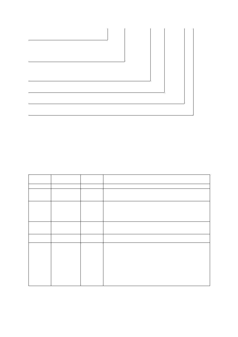
This documentation is valid for 8200 motec controllers as of version
E82MV
xxx
_
x
B xxx
XX
XX
3x
Type
Power
(e.g. 152 = 15
´ 10
2
W = 1.5 kW)
(e.g. 113 = 11
´ 10
3
W = 11 kW)
Voltage class
2 = 240 V
4 = 400 V/500 V
Device version
Hardware version
Software version
When 8200 motec controllers are operated together with Lenze motors or Lenze geared motors, these instructions
are only valid together with the operating instructions for the motors and geared motors.
In the event of service, please state the exact type designation. The function module used can either be identified
through the keypad, the PC , or by means of the nameplate stuck on the carrier housing. Moreover, each function
module is clearly designated (e.g. STANDARD" for standard I/O).
What is new / what has changed in the Operating Instructions?
Material num-
ber
Edition
Important
Contents
00402783
1.0 07/98 TD00
1. edition
First edition for pilot series
00404604
2.0 11/98 TD00
2. edition
Replaces
402783
Complete revision for series
All chapters: error correction and complete editorial revision
00422543
3.0 09/01 TD02
3. edition
Replaces
404604
Extended by frequency inverter 0.25 kW/0.37 kW and 3 kW ... 7.5 kW,
Chapter 3 Technical data": extended by powers 0.25/0.37 kW u. 3..7.5 kW
Chapter. 5 Commissioning": extended by step for step commissioning
Chapter 12 Accessories": extended and updated
All chapters: update, error correction and complete editorial revision
00459196
4.0 11/02 TD01
4. edition
Replaces
422543
Change of company name
4.1 02/03 TD15
Replaces
459196
Chapter 11 "Braking operation": update
13206840
5.1 07/07 TD14
5. edition
Extended by device version with electronic switching output K1
Chapter 4.2.1.5, 8, 11.2: update
Chapter 4.2.2.5: removed; chapter 4.2.4.4: reference to Communication Manual
Chapter 5.4 − 5.5: internal reorganisation
Chapter 11.3.2 u 11.3.3: update of brake resistor data
Chapter 14: signal flow diagrams (without AIF) updated/newly arranged and code table
updated according to SW 3.7
Layout corrections:
Chapter 13.1: Table of the application−specific configuration:
− Correction of mixed up example values in code 412/1 and 412/5
− Supplement of code 0415
E 2006 Lenze Drive Systems GmbH
No part of this documentation may be copied or made available without the explicit written approval of Lenze Drive Systems GmbH.
We have compiled all information in this documentation with great care and have checked them with regard to compliance with the hardware and software
described. Nevertheless, we cannot entirely exclude deviations. We do not accept legal responsibility or liability for damage possibly resulting therefrom.
We will include necessary amendments in the subsequent editions.
Version
5.2
08/2007