6 code table, Appendix, Code table – Lenze 8200 motec frequency inverter 0.25kW-7.5kW User Manual
Page 211
Appendix
Code table
14−10
L
EDB82MV752 EN 5.2
14.6
Code table
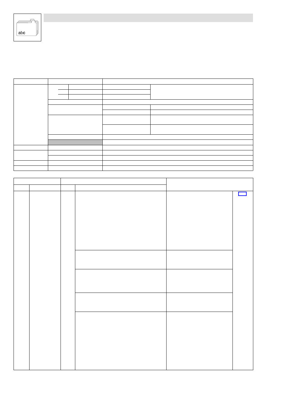
How to read the code table
Column
Abbreviation
Meaning
Code
Cxxxx
Code Cxxxx
·
The parameter value of a code can be different in every parameter
set.
·
Parameter value accepted immediately (ONLINE)
1
Subcode 1 of Cxxxx
2
Subcode 2 of Cxxxx
*
Parameter value of the code is the same in all parameter sets
v
Keypad E82ZBC
Changed parameters will be accepted after pressing
v
Keypad XT EMZ9371BC
Changed parameters will be accepted after pressing
T V
s
Keypad E82ZBC
Changed parameters will be accepted after pressing
v
if the
controller is inhibited
Keypad XT EMZ9371BC
Changed parameters will be accepted after pressing
T V
if
the controller is inhibited
(A)
Code, subcode or selection are only available when using an Application−I/O
uSEr
With Lenze setting the code is available in the USER−menu
Name
Name of the code
Lenze
Lenze setting (value at delivery or after restoring the delivery state with C0002)
à
Further information can be obtained from "IMPORTANT"
Selection
1
{%}
99
Min. value
{unit}
Max. value
IMPORTANT
−
Brief, important explanations
Code
Possible settings
IMPORTANT
No.
Name
Lenze
Selection
C0001
v
Selection of
setpoint entry
(operating mode)
0
·
Changing C0001 will cause the changes
mentioned below under C0412 and
C0410, if no free configuration under
C0412 was made before.
·
In the event that a free configuration
was made under C0412 (verification =
C0005 = 255), C0001 does not
influence C0412 and C0410. The signals
must be linked manually.
·
Free configuration under C0412 or
C0410 does not change C0001!
·
The control can be realised via terminals
or PC/keypad
^ 7−32
0
Setpoint entry via AIN1 (X3/8 or X3/1U, X3/1I)
·
C0412/1 and C0412/2 are linked with
the analog input 1(C0412/1 = 1,
C0412/2 = 1).
·
C0410 is not changed.
1
Setpoint entry via keypad or parameter channel
of an AIF bus module
·
Under C0412 the linkage with the
analog input is separated (C0412/1 =
255, C0412/2 = 255).
·
Setpoint selection via C0044 or C0046.
·
C0410 is not changed.
2
Setpoint selection via AIN1 (X3/8 or X3/1U, X3/1I)
·
C0412/1 and C0412/2 are linked with
the analog input 1 (C0412/1 = 1,
C0412/2 = 1)
·
C0410 is not changed.
3
Setpoint selection via process channel of an AIF
bus module
·
C0001 = 3 must be set to select a
setpoint via a process data channel of
an AIF bus module (types 210x, 211x,
213x, 217x)! Otherwise the process data
will not be evaluated.
·
C0412/1 and C0412/2 are linked with
the analog input words AIF−IN.W1 and
AIF−IN.W2 (C0412/1 = 10, C0412/2 =
11).
·
C0410/1 ... C0410/16 are linked with
the single bit of the AIF control word
(AIF−CTRL) (C0410/1 = 10 ...
C0410/16 = 25)