14 appendix, 1 signal flow diagrams, Appendix – Lenze 8200 motec frequency inverter 0.25kW-7.5kW User Manual
Page 202
Appendix
Signal flow charts − Standard I/O
14−1
L
EDB82MV752 EN 5.2
14
Appendix
14.1
Signal flow diagrams
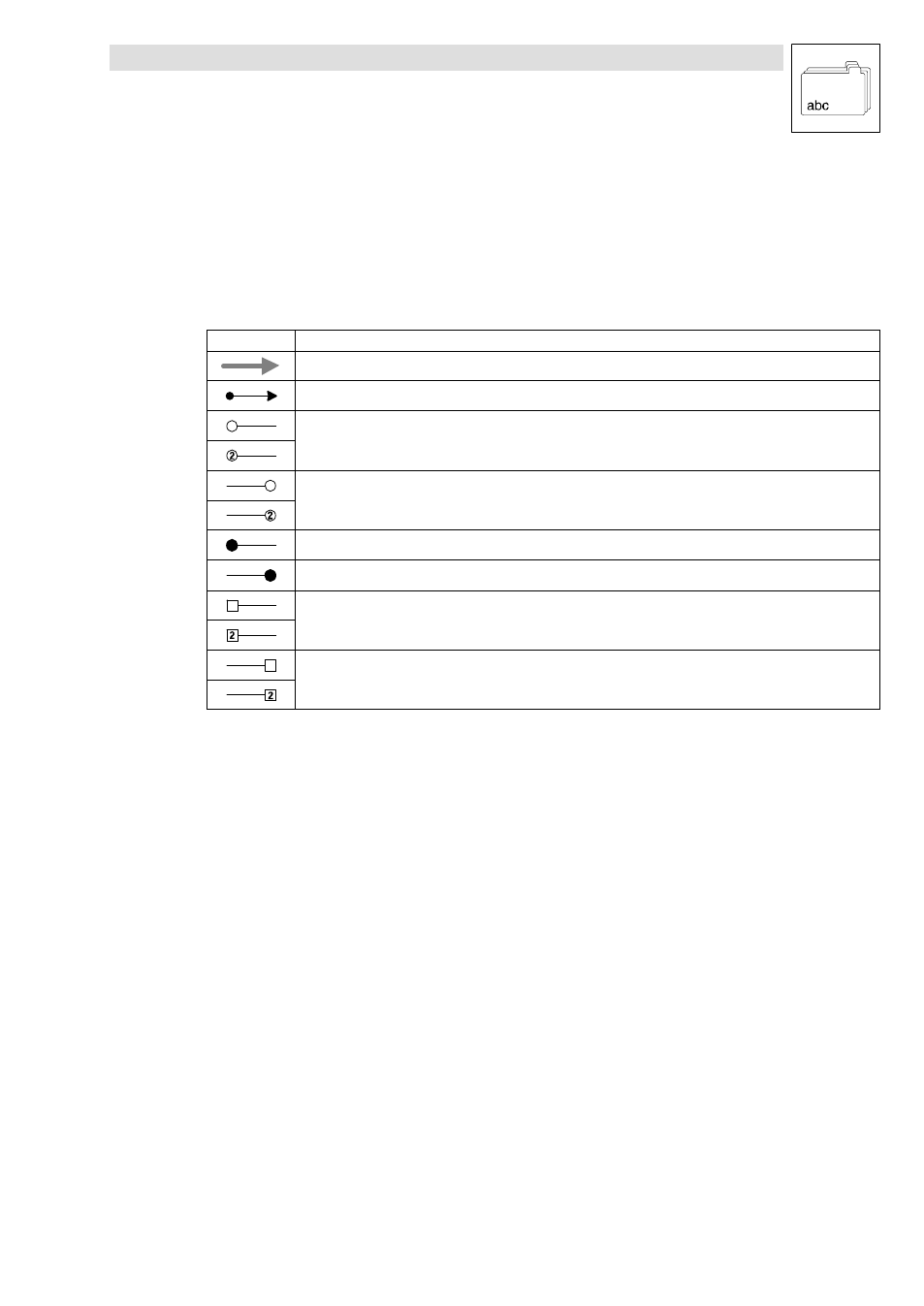
How to read the signal flow diagrams
Symbol
Meaning
Signal combination in the Lenze setting
Fixed signal combination
Analog input, can be freely connected with an analog output with the same identification
Analog output
Analog input to be used to connect the motor potentiometer output
Motor potentiometer output
Digital input, can be freely connected with a digital output with the same identification
Digital output
See also other documents in the category Lenze Hardware:
- ESMD smd tmd remote keypad (4 pages)
- EPM Programmer EEPM1RA (114 pages)
- ESMDC (36 pages)
- SMD Frequency Inverter 0.37kW-22kW (116 pages)
- SMD Frequency Inverter: Basic I/O with CANopen 0.25kW-4.0kW (36 pages)
- SMD 0-25kW-4-0kW (112 pages)
- smd Series Drives (32 pages)
- ESV SMV remote keypad H0 (2 pages)
- ESV SMV remote keypad H1 (2 pages)
- SV SMV additional I-O module (14 pages)
- EEPM1RA EPM (26 pages)
- SMVector RS-485 LECOM (29 pages)
- E84AYM10S (4 pages)
- E84AYCET EtherCAT MCI module (109 pages)
- EZAMBKBM (6 pages)
- E84AYCEC (89 pages)
- ERBPxxxRxxxx Brake resistor 200W-300W (134 pages)
- E84AYCPM (115 pages)
- E84AYCEO (165 pages)
- E84AYCER (94 pages)
- E84AVSCx 8400 StateLine C (76 pages)
- EZVxxxx-000 Power supply unit AC 230V 5A-20A (62 pages)
- E84AYCIB (75 pages)
- E82ZWBRB (48 pages)
- EZVxx00−001 Power supply unit AC 400V 5A-20A (64 pages)
- E82ZWBRE (64 pages)
- EZAEBK1001 (94 pages)
- E94AYAE SM301 (134 pages)
- E94AYAE SM301 (74 pages)
- E94AYAE SM301 (140 pages)
- E94AZPS (114 pages)
- E94AYCIB (78 pages)
- E94AYCIB (124 pages)
- E94AZEX100 (84 pages)
- EZS3-xxxA200 Sinusoidal filter 115-150A (44 pages)
- E94AZHA0051 (104 pages)
- E94AZCDM030 (72 pages)
- EZS3-xxxA200 Sinusoidal filter 180-480A (74 pages)
- E94AYCCA (114 pages)
- E94AYCCA (188 pages)
- E94AZHB0101 (104 pages)
- E94AYCPM (125 pages)
- E94AYCPM (114 pages)
- E94AYCET (140 pages)
- E94AYCET (103 pages)