Application examples, Speed control, Application−specific configuration – Lenze 8200 motec frequency inverter 0.25kW-7.5kW User Manual
Page 196: Basic settings
Application examples
Speed control
13−11
l
EDB82MV752 EN 5.2
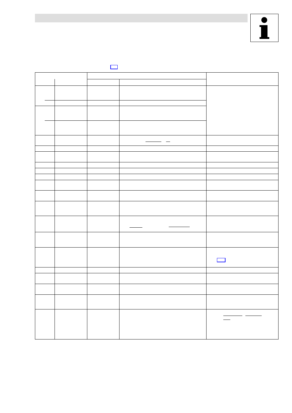
Application−specific configuration
·
Basic settings.
(
^ 6−2)
Code
Settings
Important
Value
Meaning
C0410 Free configuration
of digital input
signals
Configuration of frequency input X3/E1
24 DFIN1−ON
−1−
C0412 Free configuration
of analog input
signals
Analog signal source
5 Actual process
controller value
(PCTRL1−ACT)
−2−
C0011 Maximum output
frequency
(1
)
C0074 [%]
100
)
@
p
60
@ n
max
p = number of pole pairs
n
max
= required maximum speed [rpm]
C0014
↵ Operating mode
−2
V/f characteristic control
Dynamics in "vector control" mode too low
C0019 Operating threshold
auto DCB
approx. 0.5 Hz
Adaptation to the application
C0021 Slip compensation
0 %
No slip compensation with controlled operation
C0035*
↵ DCB selection
−1−
Brake current selection under C0036
C0036 Voltage/current DCB
50 ... 100 %
Adaptation to the application
C0070 Process controller
gain
1 ... 15
5 = typical
C0071 Process controller
reset time
50 ... 500 ms
100 ms = typical
C0072 Differential
component of
process controller
0
Not active
C0074 Process controller
influence
2 ... 10 %
S
N
+
n
0
* n
N
n
0
Example
S
N
+
1500
* 1400
1500
+ 6.67 %
·
Adaptation to the application
·
Set 200% rated motor slip (2 * S
N
)
C0106 Hold time auto DCB
1 s
·
Guide value
·
Afterwards the controller sets controller
inhibit
C0181* Process controller
setpoint 2
(PCTRL1−SET2)
·
Adaptation to the application
·
Selection with keypad or PC
·
^ 7−53: Further options for selecting the
setpoint
C0196*
↵ Activation auto DCB
−1−
DCB active when C0050 < C0019 and setpoint < C0019
C0238
↵ Frequency
precontrol
−1−
With frequency feedforward control
C0239
↵ Lower frequency
limitation
0 Hz
unipolar, no reversal of rotation direction
C0425
↵* Configuration of
frequency input
X3/E1 (DFIN1)
Set C0425 so that, at maximum motor speed,
the frequency supplied by the encoder is lower
than f
max
C0426* Frequency input
gain X3/E1, X3/E2
(A) (DFIN1−GAIN)
100
−1500.0
{0.1 %}
1500.0
C0426
+
f
N
(C0425)
nmax
60 s
@ incńrev
@
C0011
* f
s
C0011
@ 100 %
·
n
max
= maximum motor process speed in
rpm
·
f
s
= slip frequency in Hz