2 analog setpoints via terminal, Analog setpoints via terminal, Function library – Lenze 8200 motec frequency inverter 0.25kW-7.5kW User Manual
Page 105
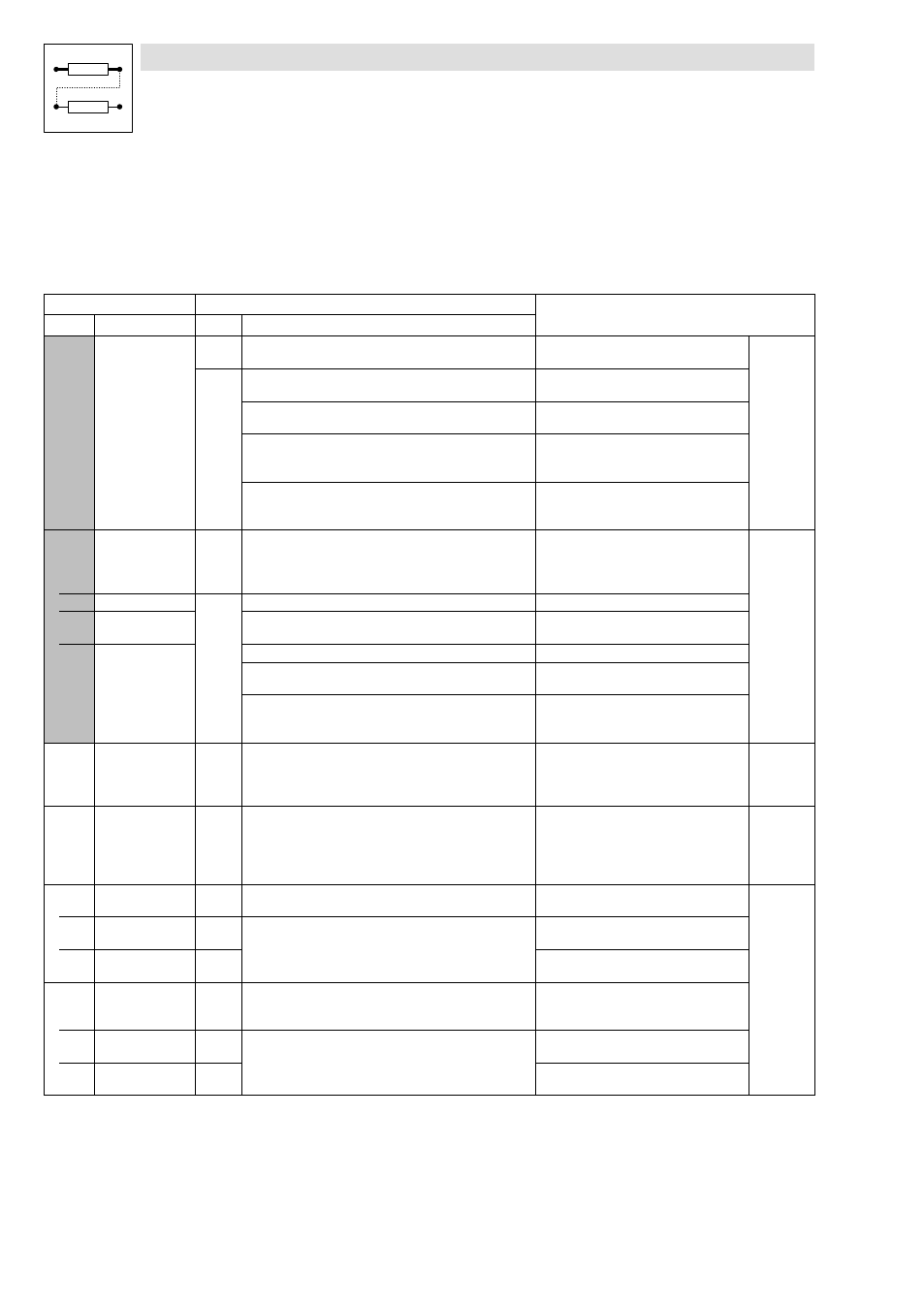
Function library
Configuration of analog and digital setpoints and actual values
7−34
L
EDB82MV752 EN 5.2
7.6.2
Analog setpoints via terminal
Description
Selection and adjustment of analog signals via terminal as setpoint or actual value.
Codes for parameter setting
Code
Possible settings
IMPORTANT
No.
Name
Lenze
Selection
C0034*
v
uSEr
Setpoint selection
range
Standard–I/O (X3/8)
−13−
Observe the switch position of the function
module!
^ 7−34
0
0
Unipolar voltage 0 ... 5 V / 0 ... 10 V
Current 0 ... 20 mA
1
Current 4 ... 20 mA
Changing the direction of rotation is only
possible with a digital signal.
2
Bipolar voltage −10 V ... +10 V
·
Minimum output frequency (C0010) not
effective
·
Individual adjustment of offset and gain
3
Current 4 ... 20 mA open−circuit monitored
TRIP Sd5, if I < 4 mA
Changing the direction of rotation is only
possible with a digital signal.
C0034*
v
(A)
uSEr
Setpoint selection
range
Application I/O
Observe the jumper setting of the function
module!
^ 7−34
1 X3/1U, X3/1I
0
0
Unipolar voltage 0 ... 5 V / 0 ... 10 V
2 X3/2U, X3/2I
1
Bipolar voltage −10 V ... +10 V
Minimum output frequency (C0010) not
effective
2
Current 0 ... 20 mA
3
Current 4 ... 20 mA
Changing the direction of rotation is only
possible with a digital signal.
4
Current 4 ... 20 mA open−circuit monitored
Changing the direction of rotation is only
possible with a digital signal.
TRIP Sd5 if I < 4 mA
C0026*
Offset analog input
1 (AIN1–OFFSET)
0.0
−200.0
{0.1 %}
200.0
·
Settings for X3/8 and X3/1U, X3/1I
·
The max. limit of the setpoint value
range of C0034 equals 100 %
·
C0026 and C0413/1 are identical
^ 7−34
C0027*
Gain analog input 1
(AIN1−GAIN)
100.0
−1500.0
{0.1 %}
1500.0
·
Settings for X3/8 and X3/1U, X3/1I
·
100.0 % = Gain 1
·
Inverse setpoint selection by negative
gain and negative offset
·
C0027 and C0414/1 are identical
^ 7−34
C0413* Offset − analog
inputs
−200.0
{0.1 %}
200.0 The upper limit of the setpoint range from
C0034 corresponds to 100 %
^ 7−34
1 AIN1−OFFSET
0.0
Setting for X3/8 or X3/1U, X3/1I
C0413/1 and C0026 are the same
2 AIN2−OFFSET
0.0
Setting for X3/2U, X3/2I
(only application I/O)
C0414* Gain − analog
inputs
−1500.0
{0.1 %}
1500.0
·
100.0 % = gain 1
·
Inverted setpoint selection through
negative gain and negative offset
1 AIN1−GAIN
100.0
Setting for X3/8 or X3/1U, X3/1I
C0414/1 and C0027 are the same
2 AIN2−GAIN
100.0
Setting for X3/2U, X3/2I
(only application I/O)