Appendix, Code table – Lenze 8200 motec frequency inverter 0.25kW-7.5kW User Manual
Page 225
Appendix
Code table
14−24
L
EDB82MV752 EN 5.2
Code
IMPORTANT
Possible settings
No.
Selection
Lenze
Name
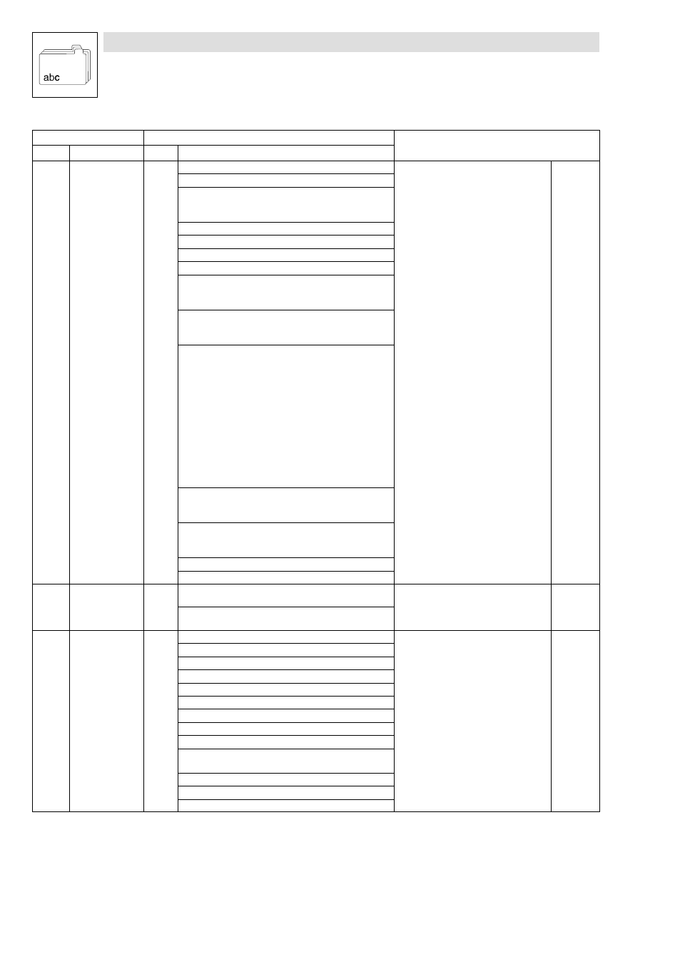
C0150
*
Controller status
word 1 (parameter
channel)
Bit
Assignment
·
Scan of the controller status via
parameter channel. The most important
status information are grouped as bit
pattern.
·
Some bits can be freely assigned to
internal digital signals
·
Configuration in C0417
·
In keypad: display only (hexadecimal)
0
Mapping of C0417/1
1
0
1
Pulse inhibit (DCTRL1−IMP)
Power outputs enabled
Power outputs inhibited
2
Mapping of C0417/3
3
Mapping of C0417/4
4
Mapping of C0417/5
5
Mapping of C0417/6
6
0
1
Output frequency = 0 (DCTRL1−NOUT=0)
false
true
7
0
1
Controller inhibit (DCTRL1−CINH)
Controller enabled
Controller inhibited
11|10|9|8 Controller status
0000 Controller initialization
0001 Mains voltage off (at external supply of the
control section ofthe drive controller)
0010 Switch−on inhibit
0011 Operation inhibited
0100 Flying−restart circuit active
0101 DC−injection brake active
0110 Operation enabled
0111 Message active
1000 Active error
12
0
1
Overheat warning (DCTRL1−OH−WARN)
No warning
J
max
− 5
°C reached
13
0
1
DC−bus overvoltage (DCTRL1−OV)
No overvoltage
Overvoltage
14
Mapping of C0417/15
15
Mapping of C0417/16
C0151
*
Controller status
word 2 (parameter
channel)
Bit
Assignment
·
The bits can be freely assigned to
internal digital signals
·
Configuration in C0418
·
In keypad: display only (hexadecimal)
0 ... 15
Mapping of C0418/1 ... C0418/16
C0155
*
Extended status
word
Bit
Assignment
0
not ready for operation (NOT DCTRL−RDY)
1
not assigned
2
I
max
(MCTRL1−IMAX)
3
Pulse inhibit (DCTRL1−IMP)
4
not assigned
5
Controller inhibit (DCTRL1−CINH)
6
TRIP (DCTRL1−TRIP)
7
not assigned
8
Collective message
(DCTRL1−OH−PTC−LP1−FAN1−WARN)
9
PAR B0 (DCTRL1−PAR−B0)
10
PAR B1 (DCTRL1−PAR−B1)
11 ... 15
Reserved