3 speed control, Application examples, Speed control – Lenze 8200 motec frequency inverter 0.25kW-7.5kW User Manual
Page 195: Speed sensor requirements
Application examples
Speed control
13−10
l
EDB82MV752 EN 5.2
13.3
Speed control
Tip!
Lenze three−phase AC motors and Lenze geared motors can be supplied with the Lenze pulse
encoder ITD21 (512/2048 increments, HTL output signals). This makes it possible to set up a
two−track speed feedback (tracks A and B) when using the application I/O function module.
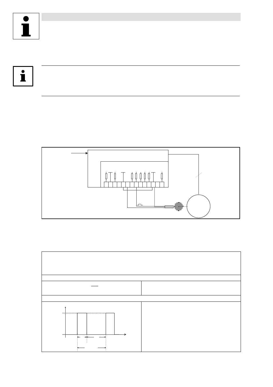
Example
Speed control with inductive single−track three−wire sensor
The speed control is designed to correct the deviation between the actual speed and the setpoint
speed caused by the effect of the load (motive and generative).
In order to detect the motor speed, the inductive sensor scans e.g. a gear, a metallic fan impeller or
cam. Scanning should take place directly on the motor or within the machine.
6 2
8
9
7
2 0 2 8 E 1
A 1
E 4
E 3
E 2
3 9
+ 5 V
G N D 2
8 2 0 0
M
3 ~
3
7
5 9
G N D 1
+ 2 0 V
G N D 1
Q
R
S t a n d a r d - I / O
Fig. 13−4
Speed control with three−wire sensor
setpoint
three−wire sensor
8200:
8200 motec or 8200 vector
Speed sensor requirements
·
The maximum frequency of inductive sensors generally ranges from 1 ... 6 kHz depending on the type.
·
At the detection point, the number of attenuation cams per revolution must ensure an output frequency of the sensor as high as possible.
·
The control dynamics will be sufficient if the output frequency (f
act
) is > 0.5 kHz at rated speed.
·
If the current consumption of the sensor is not higher than the value permitted at X3/20, a three−wire sensor can be directly connected to
the controller.
Output frequency calculation
f
act
+
z
@ n
60
z = number of cams per revolution
n = speed at the detection point [rpm]
f
act
= output frequency of the sensor in [Hz]
Permissible pulse shape at X3/E1
T ³ 1 0 0 m s
T e
T a
1 5 V
U
E 1
t
0
0
·
Te = on (HIGH)
·
Ta = off (LOW)
Permissible level range:
·
LOW: 0 ... +3 V
·
HIGH: +12 ... +30 V
Permissible range of the scanning ratio
·
Te : Ta = 1 : 1 to Te : Ta = 1 : 5
Tip!
You can use every speed sensor which meets the level and scanning
ratio requirements.