9 designing a wide ultra scsi system, Designing a wide ultra scsi system, Determining the synchronous transfer rate – Avago Technologies LSI53C876E User Manual
Page 54: Figure 2.7
2-32
Functional Description
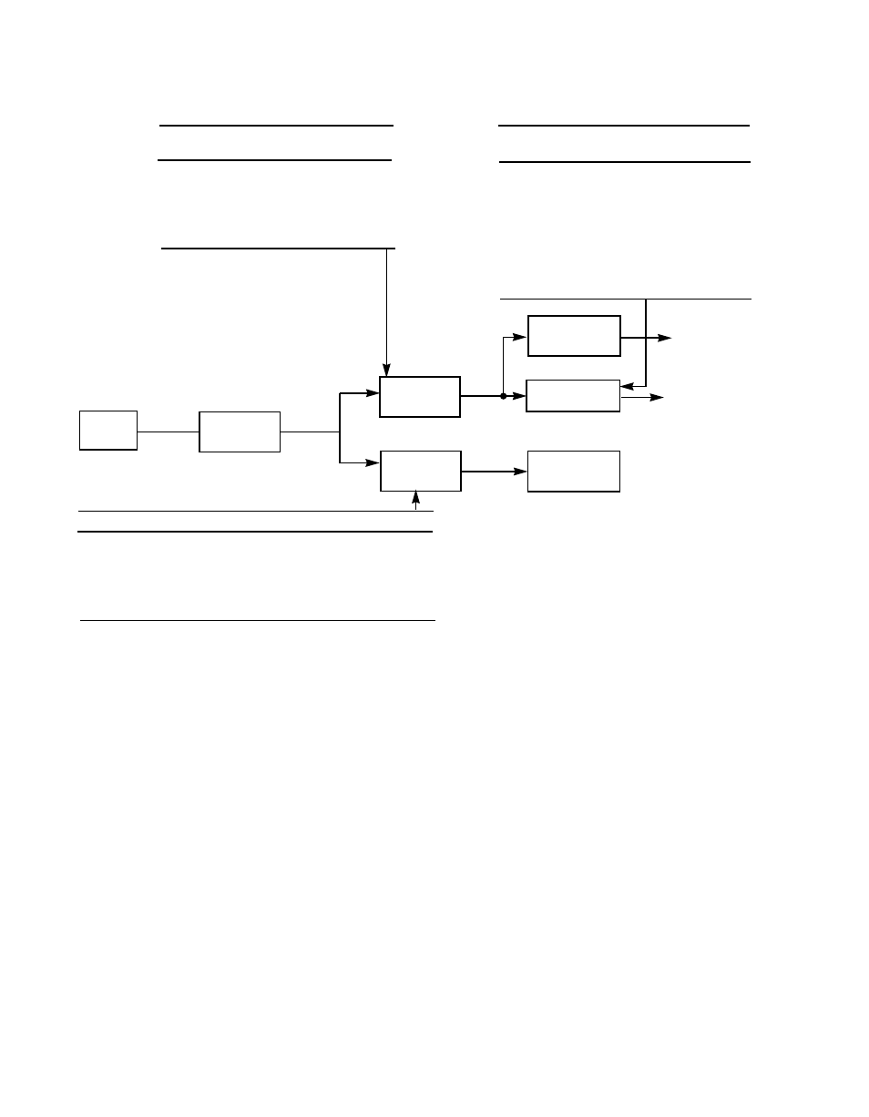
Figure 2.7
Determining the Synchronous Transfer Rate
2.2.9 Designing a Wide Ultra SCSI System
Migrating an existing SCSI design from Fast SCSI to Wide Ultra SCSI
requires minor software modifications as well as consideration for some
hardware design guidelines. Since Wide Ultra SCSI is based on existing
SCSI standards, it can use existing software programs as long as the
software is able to negotiate for Wide Ultra SCSI synchronous transfer
rates.
In the area of hardware, the primary area of concern in SE systems is
to maintain signal integrity at high data transfer rates. To assure reliable
operation at Wide Ultra SCSI transfer speeds, follow the system design
parameters recommended in the Wide Ultra SCSI Parallel Interface draft
standard.
Chapter 6, “Electrical Characteristics,”
contains Wide Ultra
SCLK
SCF
Divider
CCF
Divider
Synchronous
Divider
Asynchronous
SCSI Logic
Divide by 4
SCF2
SCF1
SCF0
SCF
Divisor
0
0
1
1
0
1
0
1.5
0
1
1
2
1
0
0
3
0
0
0
3
TP2
TP1
TP0
XFERP
Divisor
0
0
0
4
0
0
1
5
0
1
0
6
0
1
1
7
1
0
0
8
1
0
1
9
1
1
0
10
1
1
1
11
CCF2
CCF1
CCF0
Divisor
0
0
1
1
0
1
0
1.5
0
1
1
2
1
0
0
3
0
0
0
3
Example:
SCLK = 40 MHz, SCF = 1, XFERP = 4,
SCSI transfer rate = 10 MHz, CCF = 2
This point
must not
exceed
80 MHz
Receive
Clock
This point
must not
exceed
25 MHz
(40 MHz 1 = synchronous core rate)
(40 MHz 4 = 10 MHz synchronous rate =
10 Mbytes/s on an 8-bit SCSI bus)
Send
Clock
To
SCSI Bus
CLK
Doubler
40 MHz