N in, Figure 13–1, If the w – Altera Arria V Hard IP for PCI Express User Manual
Page 208
13–2
Chapter 13: Flow Control
Throughput of Posted Writes
Arria V Hard IP for PCI Express
December 2013
Altera Corporation
User Guide
Each receiver also maintains a credit allocated counter which is initialized to the total
available space in the RX buffer (for the specific Flow Control class) and then
incremented as packets are pulled out of the RX buffer by the Application Layer. The
value of this register is sent as the FC Update DLLP value.
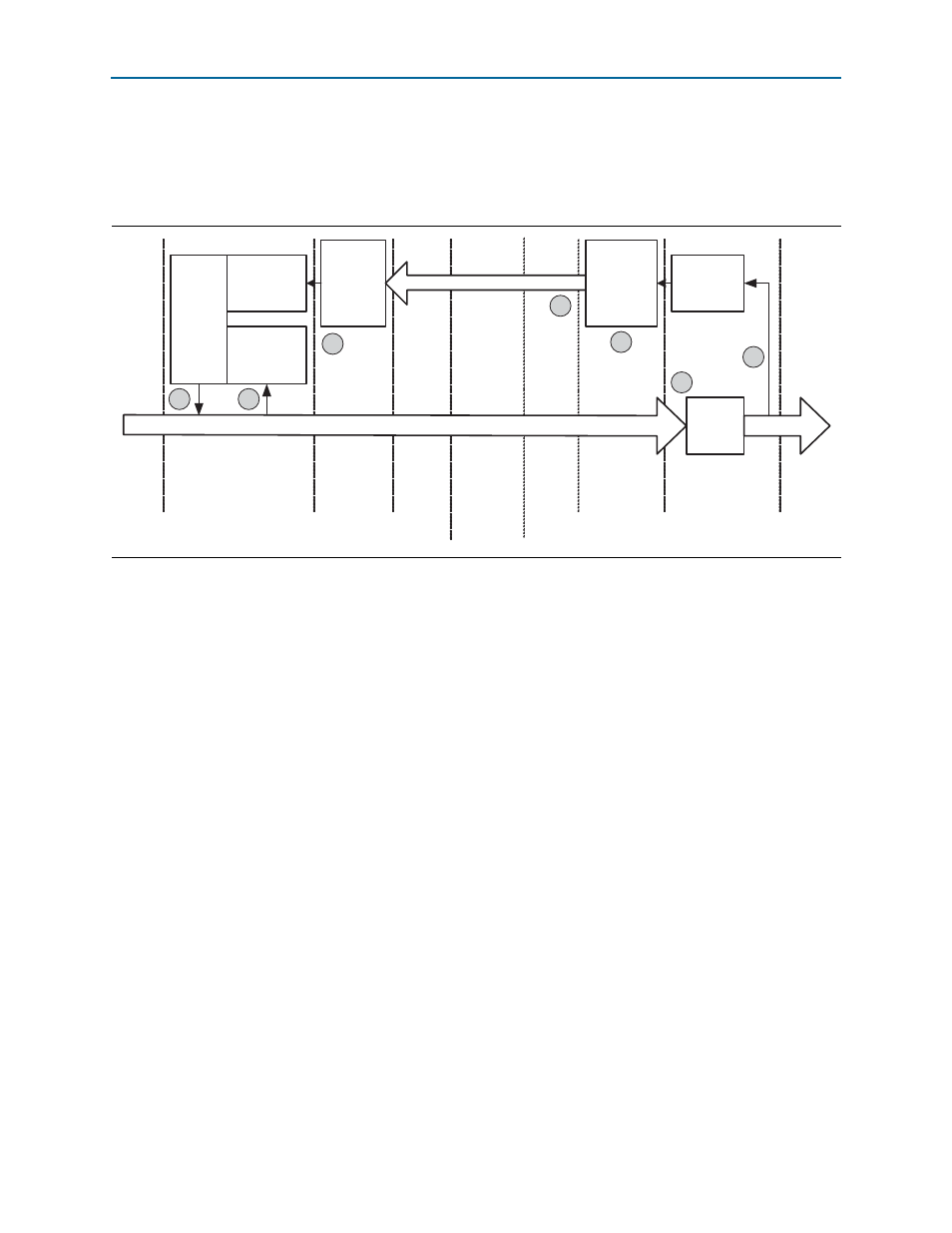
The following numbered steps describe each step in the Flow Control Update loop.
The corresponding numbers on
show the general area to which they
correspond.
1. When the Application Layer has a packet to transmit, the number of credits
required is calculated. If the current value of the credit limit minus credits
consumed is greater than or equal to the required credits, then the packet can be
transmitted immediately. However, if the credit limit minus credits consumed is
less than the required credits, then the packet must be held until the credit limit is
increased to a sufficient value by an FC Update DLLP. This check is performed
separately for the header and data credits; a single packet consumes only a single
header credit.
2. After the packet is selected for transmission the
Credits
Consumed
Register
is
incremented by the number of credits consumed by this packet. This increment
happens for both the header and data
Credit
Consumed
Registers
.
3. The packet is received at the other end of the link and placed in the RX buffer.
4. At some point the packet is read out of the RX buffer by the Application Layer.
After the entire packet is read out of the RX buffer, the
Credit
Allocated
Register
can be incremented by the number of credits the packet has used. There are
separate
Credit
Allocated
Registers
for the header and data credits.
5. The value in the
Credit
Allocated
Registers
is used to create an FC Update
DLLP.
Figure 13–1. Flow Control Update Loop
Credits
Consumed
Counter
Credit
Limit
Data Packet
Flow
Control
Gating
Logic
(Credit
Check)
Allow
Incr
Rx
Buffer
Data Packet
Credit
Allocated
FC
Update
DLLP
Generate
FC
Update
DLLP
Decode
FC Update DLLP
App
Layer
Transaction
Layer
Data Link
Layer
Physical
Layer
Incr
Physical
Layer
Data Link
Layer
Transaction
Layer
App
Layer
Data Source
PCI
Express
Link
Data Sink
1
2
7
6
5
3
4