Lane initialization and reversal, Lane initialization and reversal –4 – Altera Arria V Hard IP for PCI Express User Manual
Page 206
12–4
Chapter 12: Optional Features
Lane Initialization and Reversal
Arria V Hard IP for PCI Express
December 2013
Altera Corporation
User Guide
Lane Initialization and Reversal
Connected components that include IP blocks for PCI Express need not support the
same number of lanes. The ×4 variations support initialization and operation with
components that have 1, 2, or 4 lanes. The ×8 variant supports initialization and
operation with components that have 1, 2, 4, or 8 lanes.
The Arria Hard IP for PCI Express supports lane reversal, which permits the logical
reversal of lane numbers for the ×1, ×2, ×4, and ×8 configurations. Lane reversal
allows more flexibility in board layout, reducing the number of signals that must cross
over each other when routing the PCB.
Table 12–3
summarizes the lane assignments for normal configuration.
Table 12–4
summarizes the lane assignments with lane reversal.
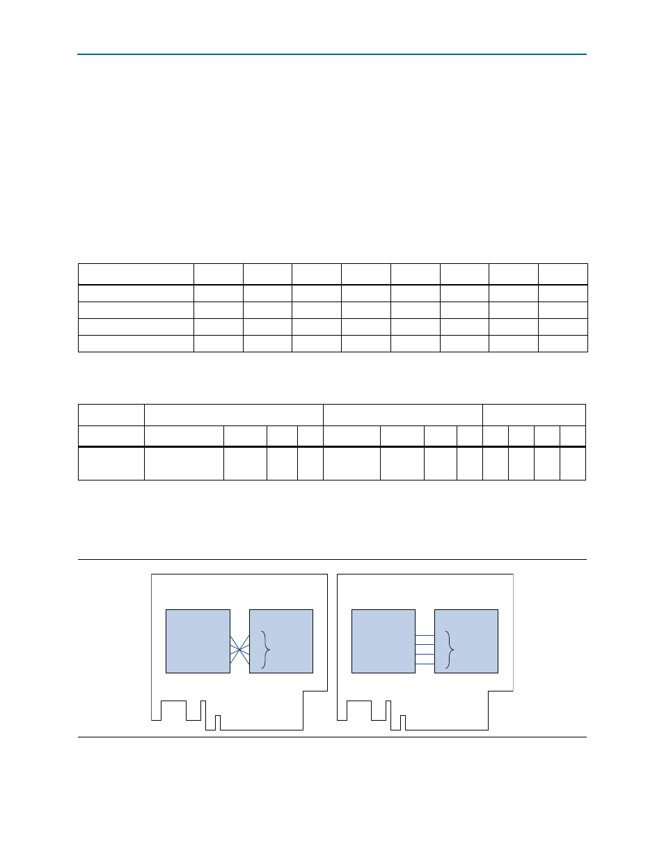
illustrates a PCI Express card with ×4 IP Root Port and a ×4 Endpoint on
the top side of the PCB. Connecting the lanes without lane reversal creates routing
problems. Using lane reversal, solves the problem.
Table 12–3. Lane Assignments without Lane Reversal
Lane Number
7
6
5
4
3
2
1
0
×8 IP core
7
6
5
4
3
2
1
0
×4 IP core
—
—
—
—
3
2
1
0
×2 IP core
—
—
—
—
—
—
1
0
×1 IP core
—
—
—
—
—
—
—
0
Table 12–4. Lane Assignments with Lane Reversal
Core Config
8
4
1
Slot Size
8
4
2
1
8
4
2
1
8
4
2
1
Lane
assignments
7:0,6:1,5:2,4:3,3:
4,2:5,1:6,0:7
3:4,2:5,
1:6,0:7
1:6,
0:7
0:7
7:0,6:1,
5:2,4:3
3:0,2:1,
1:2,0:3
3:0,
2:1
3:0
7:0
3:0
1:0
0:0
Figure 12–2. Using Lane Reversal to Solve PCB Routing Problems
0
1
2
3
Root Port
3
2
1
0
Endpoint
0
1
2
3
Root Port
0
1
2
3
Endpoint
No Lane Reversal
Results in PCB Routing Challenge
With Lane Reversal
Signals Route Easily
lane
reversal
no lane
reversal