Clocks, Clocks –4 – Altera Arria V Hard IP for PCI Express User Manual
Page 184
9–4
Chapter 9: Reset and Clocks
Clocks
Arria V Hard IP for PCI Express
December 2013
Altera Corporation
User Guide
As
Figure 9–3
illustrates, the RX transceiver reset includes the following steps:
1. After
rx_pll_locked
is asserted, the LTSSM state machine transitions from the
Detect.Quiet to the Detect.Active state.
2. When the
pipe_phystatus
pulse is asserted and
pipe_rxstatus[2:0]
= 3, the
receiver detect operation has completed.
3. The LTSSM state machine transitions from the Detect.Active state to the
Polling.Active state.
4. The Hard IP for PCI Express asserts
rx_digitalreset
. The
rx_digitalreset
signal
is deasserted after
rx_signaldetect
is stable for a minimum of 3 ms.
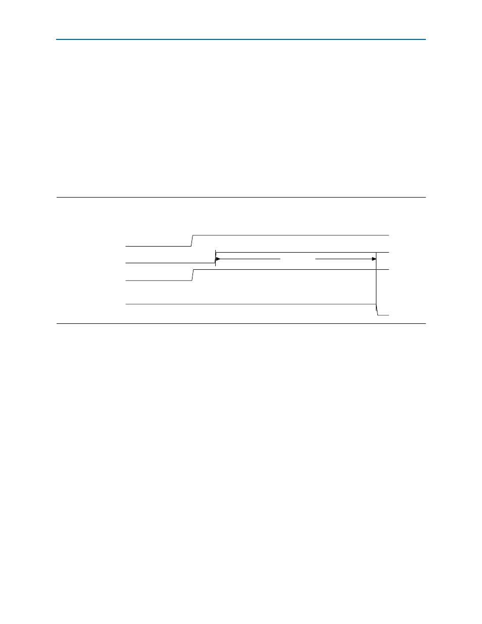
Figure 9–4
illustrates the TX transceiver reset sequence.
As
Figure 9–4
illustrates, the RX transceiver reset includes the following steps:
1. After
npor
is deasserted, the core deasserts the
npor_serdes
input to the TX
transceiver.
2. The SERDES reset controller waits for
pll_locked
to be stable for a minimum of
127 cycles before deasserting
tx_digitalreset.
1
The Arria V embedded reset sequence meets the 100 ms configuration time specified
in the
Clocks
In accordance with the
, you must provide a 100 MHz
reference clock that is connected directly to the transceiver. As a convenience, you
may also use a 125 MHz input reference clock as input to the TX PLL. The output of
the transceiver drives
coreclkout_hip
.
coreclkout_hip
must be connected back to
the
pld_clk
input clock, possibly through a clock distribution circuit required by the
specific application. For Application Layers running at 250 MHz, Altera recommends
using a PLL to ease timing closure.
Figure 9–4. TX Transceiver Reset Sequence
npor
pll_locked
npor_serdes
127 cycles
tx_digitalreset