Rockwell Automation 20Y PowerFlex 700H, 700S, and 700AFE Drive Fan Systems, Frames 9...14 User Manual
Page 99
Rockwell Automation Publication PFLEX-IN029B-EN-P - August 2014
99
PowerFlex 700H and 700S Drives - Frame 11 Procedures
Chapter 3
Main AC Fan Inverter Circuit Board (20-VB00299) and AC Output
Transformer Assembly (20-FR10845) Removal and Installation
PowerFlex 700H and 700S frame 11 drives have three fan inverters. You can
replace an AC or DC fan inverter circuit board, or replace an AC output
transformer assembly (includes the AC output transformer and AC fan capacitor
on the assembly). See Isolating a Faulty Fan Inverter on page
for test
procedures used to determine if the circuit board requires replacement.
Follow these steps to remove and replace a main fan inverter circuit board or an
AC output transformer assembly.
1.
Review the General Precautions on page
2.
Remove power from the drive. See Remove Power from the Drive on page
3.
Move the control frame and remove the air flow plate and protective
covers from the drive. See Move the Control Frame and Remove the Air
Flow Plate and Protective Covers on page
4.
Remove the appropriate main fan inverter assembly. See
on page
Removing the Main AC or DC Fan Power Supply Assemblies.
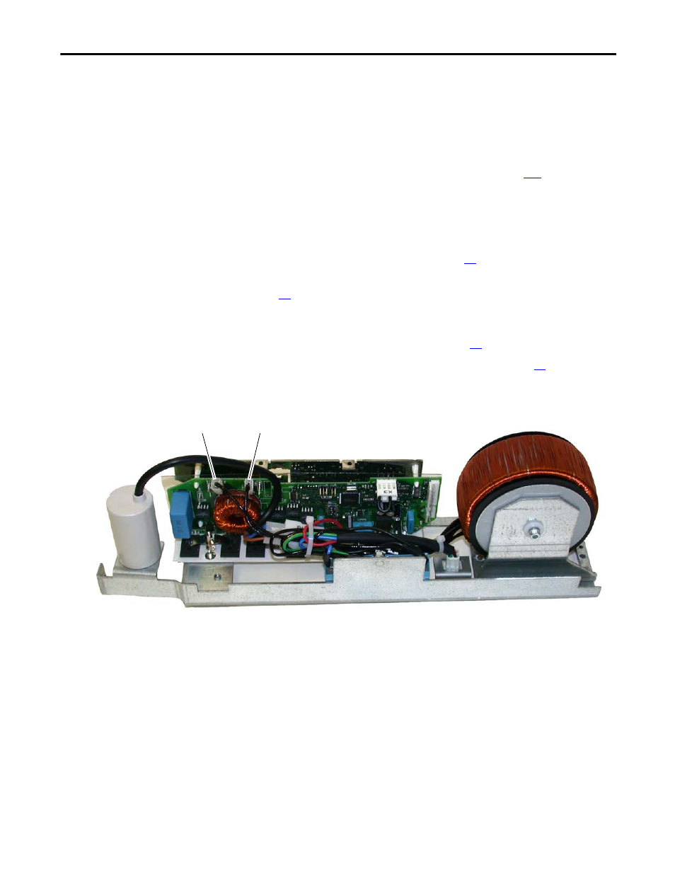
5.
Disconnect the cables from connectors X4 and X5.
X4
X5
AC Fan System Shown