Rockwell Automation 20Y PowerFlex 700H, 700S, and 700AFE Drive Fan Systems, Frames 9...14 User Manual
Page 138
138
Rockwell Automation Publication PFLEX-IN029B-EN-P - August 2014
Chapter 5
PowerFlex 700H and 700S Drives - Frame 13 Procedures
Remove the Voltage Feedback Circuit Board Assembly (Inverter Only)
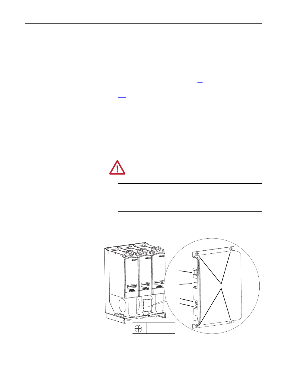
The PowerFlex 700S drive has a voltage feedback circuit board assembly located
on the fan housing of the V phase inverter section. It must be removed to service
the fan inverter circuit board and fans. Follow these steps to remove the voltage
feedback circuit board assembly.
1.
Review the General Precautions on page
2.
Remove power from the drive. See Remove Power from the Drive on page
3.
If necessary, remove the protective screens from the drive. See Move the
Control Frame, and Remove the Screens, Airflow Plates, and Protective
Covers on page
.
4.
Disconnect the DC bus connection cable from connector J2.
5.
Disconnect the motor feedback connection cable from connector J1.
6.
Carefully unplug the fiber-optic cables from sockets J4 and J5 and carefully
move them aside.
7.
Remove the four M4 x 8 mm Phillips head screws that secure the voltage
feedback circuit board assembly to the fan housing on the drive and
carefully remove the assembly.
ATTENTION: Hazard of permanent eye damage exists when using optical
transmission equipment. This product emits intense light and invisible
radiation. Do not look into fiber-optic ports or fiber-optic cable connectors.
IMPORTANT
Minimum inside bend radius for fiber-optic cable is 25.4 mm (1 in.).
Any bends with a shorter inside radius can permanently damage the
fiber-optic cable. Signal attenuation increases with decreased inside
bend radii.
J2
J1
J4
J5
7
P2
1.0 N
•
m (8.8 lb
•
in)