Rockwell Automation 20Y PowerFlex 700H, 700S, and 700AFE Drive Fan Systems, Frames 9...14 User Manual
Page 191
Rockwell Automation Publication PFLEX-IN029B-EN-P - August 2014
191
PowerFlex 700AFE Drive - Frame 10 Procedures
Chapter 7
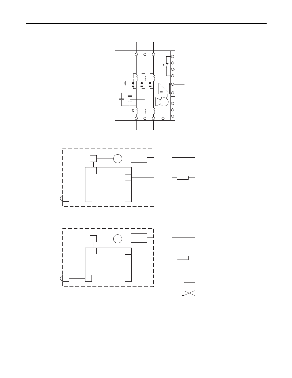
Figure 23 - Frame 10 AFE (LCL Filter Section) DC Fan System Wiring Schematic Diagram
L1
L2
L3
X52
X53
X51
U
V
W
M
1
2
3
4
+
-
1
3
5
PE
-L1
X3
X3
LCL Filter
X8
X53 (3-pin)
+ Pin = DC+ (supply)
- Pin = DC- (supply)
X4
X51 (4-pin)
Pin 5 = +16.5V
Pin 3 = (fan control)
Pin 1 = (fan alarm)
Fuse
X52 (4-pin)
Pin 1 = KLIXON
Pin 4 = KLIXON
X1
Fan
KLIXON
X1
Fan DC Power
Supply PCB
AFE Power Structure
X3 on AFE Power Structure
DC Bus
X3
LCL Filter
X8
X53 (3-pin)
+ Pin = DC+ (supply)
– Pin = DC– (supply)
X2
X51 (4-pin)
Pin 4 = +16.5V
Pin 3 = (fan control)
Pin 2 = –DC
Pin 1 = (fan alarm)
Fuse
X52 (4-pin)
Pin 1 = KLIXON
Pin 4 = KLIXON
X1
Fan
KLIXON
X81
Fan DC Power
Supply PCB
AFE Power Structure
DC Bus
X3 on AFE Power Structure
Pin 1
Pin 2
Pin 3
Flying Lead to –DC Bus
X3
LCL Filter DC Fan System Wiring -Older Version
LCL Filter DC Fan System Wiring -Newer Version
(Older version of X51
connections shown)