Rockwell Automation 20Y PowerFlex 700H, 700S, and 700AFE Drive Fan Systems, Frames 9...14 User Manual
Page 111
Rockwell Automation Publication PFLEX-IN029B-EN-P - August 2014
111
PowerFlex 700H and 700S Drives - Frame 11 Procedures
Chapter 3
DC Fan
: If the measurements are not similar to those in this table, replace
the DC fan.
6.
Remove the two M6 x 20 mm hexalobular screws that secure the fan to the
drive. Then remove the fan.
Note: The back of the fan housing contains two holes in the sheet metal
that fit onto positioning pins located on the drive frame. To remove the
main fan assemblies, lower the front end of the assembly downward in
order to clear the sheet metal on the frame, and pull the fan assembly off
the positioning pins and out of the drive.
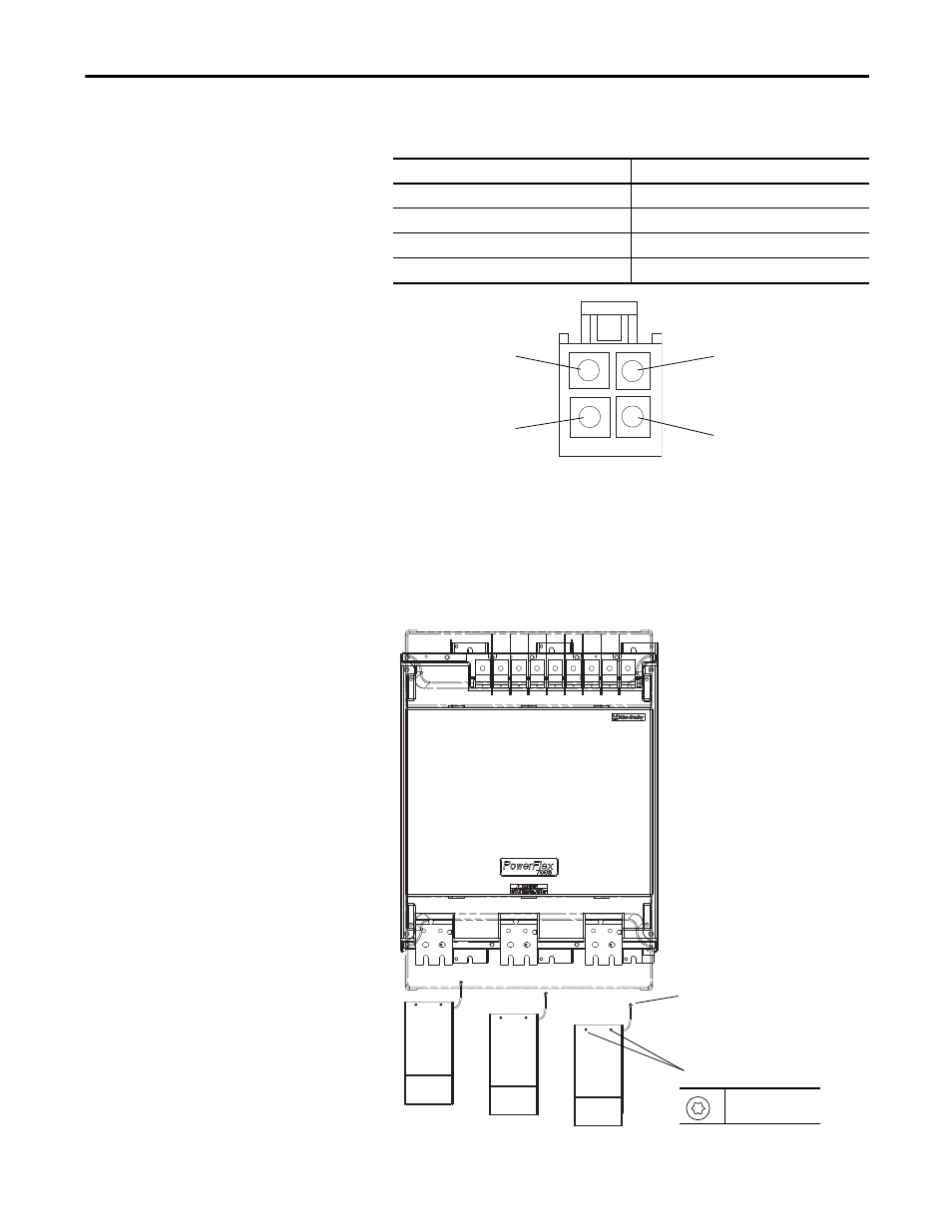
Connection wires
Resistance ±5%
Red-Blue
∞ Ω
Red-White
∞ Ω
White-Yellow
∞ Ω
Blue-White
∞ Ω
White (Tach Output) Pin 3
Red (+) Pin 1
Blue (-) Pin 4
Yellow (Control Output) Pin 2
DC Fan Pinouts
4
6
T30
4.5 N
•
m (39.8 lb
•
in)