Rockwell Automation 20Y PowerFlex 700H, 700S, and 700AFE Drive Fan Systems, Frames 9...14 User Manual
Page 98
98
Rockwell Automation Publication PFLEX-IN029B-EN-P - August 2014
Chapter 3
PowerFlex 700H and 700S Drives - Frame 11 Procedures
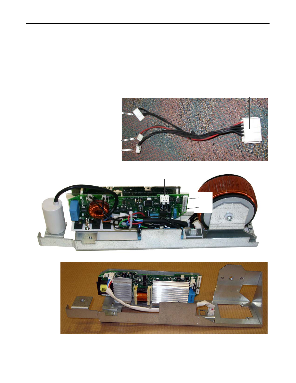
10.
For the right-side fan assembly, disconnect the cables from connectors X2
and X8 on the fan power supply circuit board. If an in-line connector is
present (as shown in the image below), disconnect the main connector
from the front of the drive.
11.
For the left-side and center fan assemblies, disconnect the cables from
connectors X2, X8, and X3. If an in-line connector is present (as shown in
the image below), disconnect the main connector from the front of the
drive.
12.
Carefully remove the fan power supply assemblies by pulling them out of
the front of the drive.
In-line Connector at Front of Drive
X8
X2
X3
X3 (Jumper Installed)
Right-side AC Fan Inverter System
X8
X2
Note: Series A Fan Capacitor Shown
Right-side DC Fan Power Supply