Rockwell Automation 20Y PowerFlex 700H, 700S, and 700AFE Drive Fan Systems, Frames 9...14 User Manual
Page 231
Rockwell Automation Publication PFLEX-IN029B-EN-P - August 2014
231
PowerFlex 700AFE Drive - Frame 10 Procedures
Chapter 7
1.
Review the General Precautions on page
2.
Remove power from the AFE. See Remove Power from the AFE on page
3.
Remove the LCL filter fan assembly from the AFE. See LCL Filter Fan
Assembly Removal and Installation on page
4.
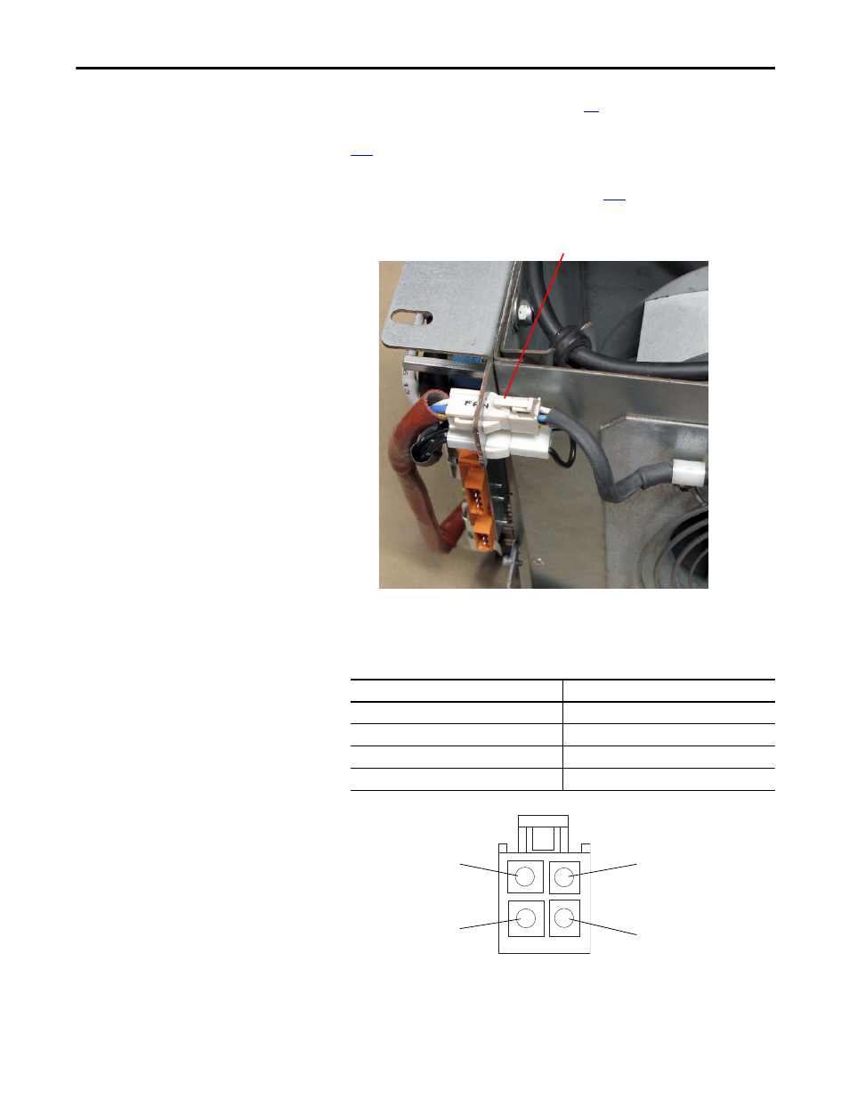
Disconnect the X1 connector from the sheet metal housing.
5.
Measure the resistance between the fan supply wires.
DC Fan
: If the measurements are not similar to those in this table, replace
the DC fan.
Connection wires
Resistance ±5%
Red-Blue
∞ Ω
Red-White
∞ Ω
White-Yellow
∞ Ω
Blue-White
∞ Ω
4
Image for SK-Y1-DCPS2-F10
White (Tach Output) Pin 3
Red (+) Pin 1
Blue (-) Pin 4
Yellow (Control Output) Pin 2
DC Fan Pinouts
This manual is related to the following products: