Rockwell Automation 20Y PowerFlex 700H, 700S, and 700AFE Drive Fan Systems, Frames 9...14 User Manual
Page 75
Rockwell Automation Publication PFLEX-IN029B-EN-P - August 2014
75
PowerFlex 700H and 700S Drives - Frame 10 Procedures
Chapter 2
3.
Move the control frame and remove the air flow plate and protective
covers from the drive. See Move the Control Frame and Remove the Air
Flow Plate and Protective Covers on page
4.
Remove the appropriate main fan inverter assembly. See Remove the Main
AC or DC Fan Power Supply Assemblies on page
.
5.
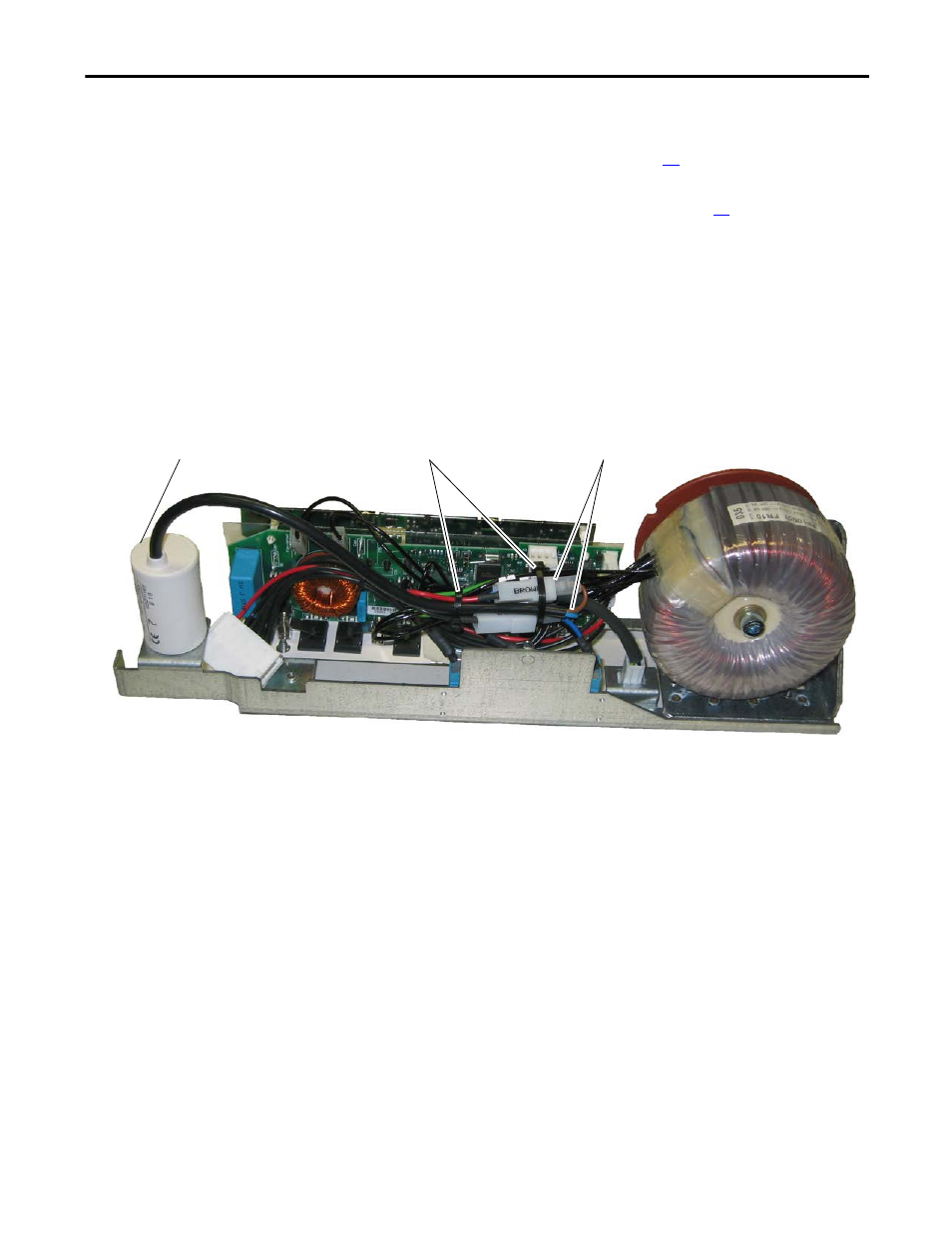
Cut the cable ties securing the wires marked Brown and Blue.
6.
Disconnect the AC fan capacitor wire connectors marked Brown and
Blue.
7.
If a series A capacitor is installed, continue with the next step. If a series B
capacitor is installed, measure the value of the capacitor. If the value of the
capacitor is less than 7
μF, continue with the next step.
8.
Unscrew and remove the fan capacitor from the AC fan inverter assembly.
6
5
8
Note: AC fan system shown