Rockwell Automation 20Y PowerFlex 700H, 700S, and 700AFE Drive Fan Systems, Frames 9...14 User Manual
Page 68
68
Rockwell Automation Publication PFLEX-IN029B-EN-P - August 2014
Chapter 2
PowerFlex 700H and 700S Drives - Frame 10 Procedures
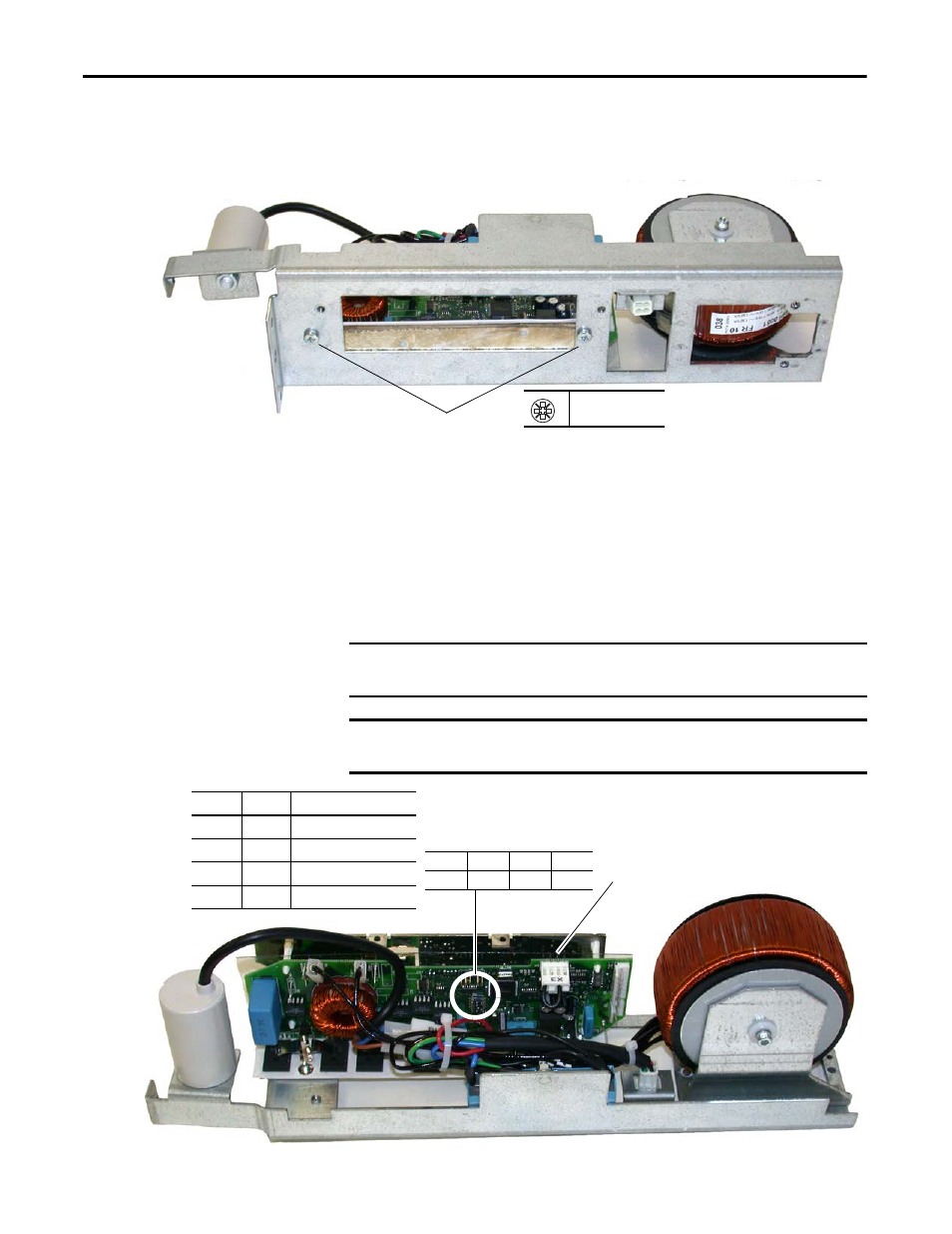
6.
Remove two M5 x 10 mm POZIDRIV screws from the bottom of the
assembly that secure the AC fan inverter board to the assembly and remove
the AC fan inverter circuit board.
7.
Complete the appropriate installation:
•
If you are replacing the AC fan inverter circuit board, install the new
circuit board on the existing AC fan inverter assembly in the reverse
order of removal.
•
If you are replacing the AC fan output transformer assembly, install the
existing fan inverter circuit board on the new AC fan output
transformer assembly in the reverse order of removal.
8.
Install the AC fan inverter assembly in the reverse order of removal.
6
PZ2
2.3 N
•
m (20.4 lb
•
in)
Right-side AC fan inverter assembly shown
IMPORTANT
Verify that dip switch S1 on the new AC fan inverter board is properly
configured, as shown below.
IMPORTANT
If you are replacing a right-side AC fan inverter circuit board, install the jumper
on connector X3.
S1-1
S1-2
S1-3
S1-4
Off
Off
On
Off
Install jumper on X3 for right-
side fan inverter boards
Switch
Setting
To indicate the following:
S1
Off
50 Hz fan motor frequency
S2
Off
220 V AC motor voltage
S3
On
230 V AC motor voltage
S4
Off
Frame size 9…14
Note: AC fan system shown