Rockwell Automation 20Y PowerFlex 700H, 700S, and 700AFE Drive Fan Systems, Frames 9...14 User Manual
Page 247
Rockwell Automation Publication PFLEX-IN029B-EN-P - August 2014
247
PowerFlex 700AFE Drive - Frame 13 Procedures
Chapter 8
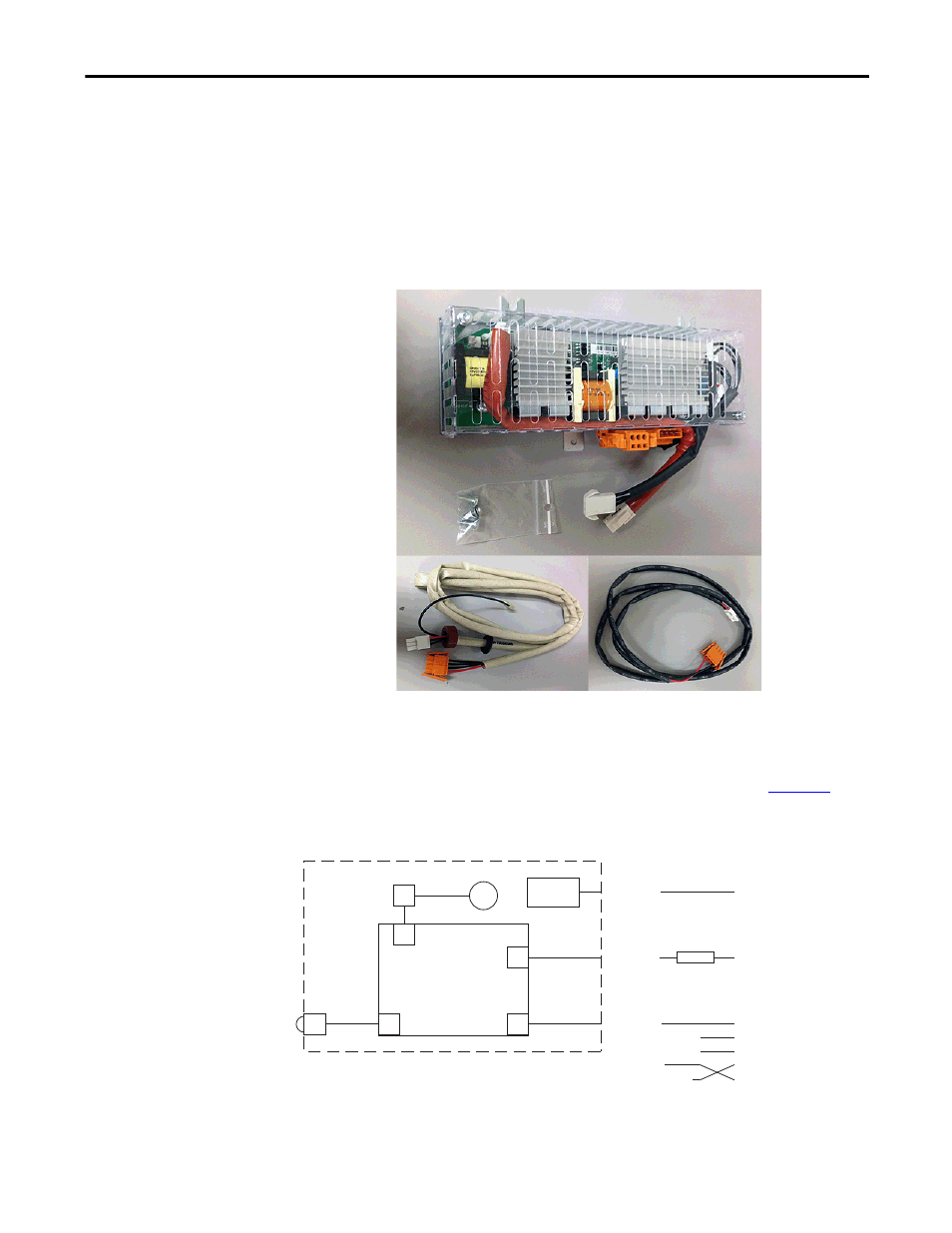
LCL Filter Fan DC Power Supply (SK-Y1-DCPS2-F13) Removal and Installation
This kit contains the following components.
•
Fan DC power supply circuit board
•
New X51 cable (fan circuit board to AFE power structure connections)
•
New X52 cable (fan motor thermal switch to AFE power structure
connections)
Note: It is not necessary to remove the fan assembly from the LCL filter, but by
doing so, it may be easier to replace the fan DC power supply circuit board.
The LCL filter fan DC power supply wiring diagram is shown in
Figure 34
. The
diagram shows the connections to the AFE power structure and DC bus.
Figure 34 - LCL Filter Fan DC Power Supply (SK-Y1-DCPS2-F13) Wiring Diagram - Newer Version
X3
LCL Filter
X8
X53 (3-pin)
+ Pin = DC+ (supply)
– Pin = DC– (supply)
X2
X51 (4-pin)
Pin 4 = +16.5V
Pin 3 = (fan control)
Pin 2 = –DC
Pin 1 = (fan alarm)
Fuse
X52 (4-pin)
Pin 1 = KLIXON
Pin 4 = KLIXON
X1
Fan
KLIXON
X81
Fan DC Power
Supply PCB
AFE Power Structure
DC Bus
X3 on AFE Power Structure
Pin 1
Pin 2
Pin 3
Flying Lead to –DC Bus
X3